Calculate force required for equilibrium, Mechanical Engineering

Assignment Help:

Calculate force required for equilibrium:

A member ABCD is subjected to the point loads P1, P2, P3  and P4  as shown in the figure given below

700_Calculate force required for equilibrium.png

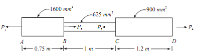
Calculate force P3 required for equilibrium if P1 = 120 kN, P2 = 220 kN and P4 = 160 kN. Determine the net change in length of member. Take E = 200 GN/m2.
Sol.: Modulus of elasticity E = 200 GN/ m2 = 2 × 10⁵ N/mm2.

By considering equilibrium of forces along axis of the member.

P1 + P3 = P2 + P4;

120 + P3 = 220 + 160

Force P3 = 220 + 160 - 120 = 260 kN

The forces which are acting on each segment of member are shown in free body diagrams shown below:

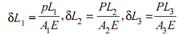
Let  δL1,  δL2 and  δL3,  be extensions in parts 1, 2 and 3 of steel bar respectively. Then,


845_Calculate force required for equilibrium1.png 
As, Tension in AB and CD but compression in BC,
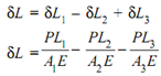
So, Total extension of the bar,
   1318_Calculate force required for equilibrium2.png 
Extension of segment AB = [(120 × 103) × (0.75 × 103)]/[1600 × (2 × 105)] = 0.28125 mm

Compression of segment BC = [(100 ×103) × (1 × 103)]/[625 × (2 × 105)] = 0.8 mm

Extension of segment CD = [(160 ×103) × (1.2 × 103)]/[900 × (2 × 105)] = 1.0667 mm

Net change in length of the member = δl =0.28125 - 0.8 + 1.0667 = 0.54795 mm (increase)        .......ANS


Related Discussions:- Calculate force required for equilibrium

Thermodynamic, what is the difference between intrinsic and extrinsic proce...

what is the difference between intrinsic and extrinsic process?

Pure maths, prove that 0 is an integer

prove that 0 is an integer

Determine the apparent range of the target - radar system, Consider radar w...

Consider radar with a PRF of 5 kHz. What is the maximum unambiguous range R ua of this radar, in km?  If a target is located at a range of 50 miles, how many pulses will the r

Shaft in parallel, SHAF T IN PARALLEL: SHAF T IN PARALLEL: The sh...

SHAF T IN PARALLEL: SHAF T IN PARALLEL: The shaft are in parallel when the driving torque is applied at the junction of shafts and resisting torque is at other ends of

Illustrate construction of hydraulic dynamometer, Illustrate working and co...

Illustrate working and construction of Hydraulic Dynamometer ? Determine Power transmitted.

Cylinder head-basic components of engine , Cylinder Head: It is fitted at...

Cylinder Head: It is fitted at top of the cylinder block. It provides space for the arrangement of spark plug, combustion chamber, camshaft, cam chain, valves and intake and exha

Laws of solid friction, Laws of solid friction: Sol.: The friction w...

Laws of solid friction: Sol.: The friction which exists between two surfaces that are not lubricated is called as solid friction. The two Surfaces can be at rest or one of t

Drag link mechanism, why there is a different angular velocity in the two c...

why there is a different angular velocity in the two cranks of a drag link mechanism?

Compute the angular velocity of bar, Compute the angular velocity of bar: ...

Compute the angular velocity of bar: A bar AB as shown in slides so that its bottom point A has a velocity of 4 m/sec to the left along the horizontal plane. Compute the veloc

Velocity and pressure, why the pressure will reduce when the velocity incre...

why the pressure will reduce when the velocity increases

Write Your Message!

Captcha
Free Assignment Quote

Assured A++ Grade

Get guaranteed satisfaction & time on delivery in every assignment order you paid with us! We ensure premium quality solution document along with free turntin report!

All rights reserved! Copyrights ©2019-2020 ExpertsMind IT Educational Pvt Ltd