Briefly explain about laplace transform, Electrical Engineering

Assignment Help:

Q. Briefly explain about Laplace transform?

Many commonly encountered excitations can be represented by exponential functions. The differential equations describing the networks are transformed into algebraic equations with the use of exponentials. The operational calculus was developed by Oliver Heaviside (1850-1925) based on a collection of intuitive rules; the transformation is, however, named after Pierre Simon Laplace (1749-1827) because a complete mathematical development of Heaviside's methods has been found in the 1780 writings of Laplace. The Laplace transformation provides a systematic algebraic approach for determining the total network response, including the effect of initial conditions. The differential equations in the time domain are transformed into algebraic equations in the frequency domain.

Frequency-domain quantities are manipulated to obtain the frequency-domain equivalent of the desired result. Then, by taking the inverse transform, the desired result in the time domain is obtained.

The single-sided Laplace transform of a function f (t) is defined by

1252_Briefly explain about Laplace transform.png

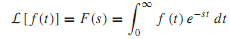
where f(t) = 0 for t< 0, and s is a complex-frequency variable given by s = σ + jω. The frequency-domain function F(s) is the Laplace transform of the time-domain function f (t).When the integral of Equation is less than infinity and converges, f (t) is Laplace transformable.

Note that for σ> 0,e-st decreases rapidly, making the integral converge. The uniqueness of the Laplace transform leads to the concept of the transform pairs,

L[f(t)] = F(s) ⇔ L-1[F(s)] = f(t)

which states that the inverse Laplace transform of F(s)is f (t). It should be noted that the Laplace transform is a linear operation such that

L[Af1(t) + Bf2(t)] = AF1(s) + BF2(s)

in which A and B are independent of s and t, and F1(s) and F2(s) are the Laplace transforms of f1(t) and f2(t), respectively.


Related Discussions:- Briefly explain about laplace transform

Explain ferrites and its uses in high frequency devices, Explain ferrites a...

Explain ferrites and its uses in high frequency devices. A group of magnetic alloys show the property of magnetisation that change, with percentage of various constituent atoms

Describe the operation of 8279, Q. Describe the operation of 8279. And als...

Q. Describe the operation of 8279. And also explain following terms: (i) N key Roll over. (ii) Key board debounce. (iii) FIFO RAM. Ans: 8279 is a programmabl

Emitter bias, Emitter bias: Figure: Emitter bias While a ...

Emitter bias: Figure: Emitter bias While a split supply (dual power supply) is accessible, this biasing circuit is the very much effective, and gives zero bias vo

Explain stator of a synchronous machine, Explain Stator of a Synchronous Ma...

Explain Stator of a Synchronous Machine? The stator of a synchronous machine is made of thin laminations of highly permeable (silicon) steel in order to reduce the core losses.

Determine the percent voltage regulation of the transformer, The transforme...

The transformer of Example is supplying full load (i.e., rated load of 50 kVA) at a rated secondary voltage of 240 V and 0.8 power factor lagging. Neglecting the exciting current o

Telecommunication, Design a low noise amplifier using an Infineon RF transi...

Design a low noise amplifier using an Infineon RF transistor BFP640. The amplifier is to be used to amplify the L2 GPS signal and so the centre frequency is 1227MHz and bandwidth 4

Calculate the magnitude of fault current, Figure shows an isolated three-ph...

Figure shows an isolated three-phase load supplied from a 33 kV/11 kV substation via a 30 km long three-phase 11 kV overhead line. The overhead line has the following series parame

Explain periodic signals and fourier series, Q. Explain Periodic Signals an...

Q. Explain Periodic Signals and Fourier Series? In the study of analog systems, predicting the response of circuits to a general time-varying voltage or currentwaveformx(t) is

Output impedance, Now that you have the input and output impedances you can...

Now that you have the input and output impedances you can design the matching networks. I will require either the Smith Charts showing how you calculated the matching components or

Write Your Message!

Captcha
Free Assignment Quote

Assured A++ Grade

Get guaranteed satisfaction & time on delivery in every assignment order you paid with us! We ensure premium quality solution document along with free turntin report!

All rights reserved! Copyrights ©2019-2020 ExpertsMind IT Educational Pvt Ltd