Bending moment :
The diagram in created shear forces, but the applied forces also create bending.
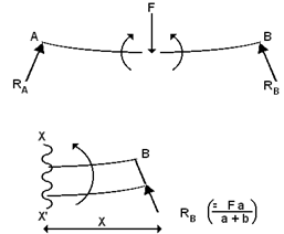
Consider a section x x' at a distance x measured from end B. Then RB creates a moment about x x', which causes a bending effect.
The Bending moment = RB . x
As with shear force, moments causing  have to be differentiated from moments causing
 . The first case is +ve bending, the second case is -ve bending.
is commonly termed "Sagging"
is commonly termed "Hogging".
Note that as distance x increases, the Bending moment also increases.
Variations in Bending Moment are often shown on a Bending Moment Diagram (BMD).
Considering the beam AB, the BMD is drawn as;
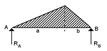
Note that in this case, the BMD is all +ve (i.e. the beam is sagging everywhere) and note also that it increases from zero as x increases to the left of B, up to a maximum and then decreases as the effect of RB is reduced by the effect of F , finally becoming zero at A.
(Note that BMD can be treated in the same way by considering distances measured to the right of A - the solutions are exactly the same).
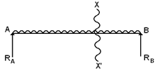
A uniformly distributed load, whilst obeying the same principles, modifies the BMD.
As x increases left of B, RB causes , but the distributed load also increases and causes
  .
.
The BMD now looks like this.
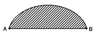
Note: Point loads create BMD's that are triangular. Distributed loads create BMD's that are curved.