BASIC PRINCIPLES :
The purpose of a propeller is to convert the power developed by the engine into a useful force called 'Thrust'. This force must be equal to and opposite in direction to 'Drag' in order for the aircraft to remain in level flight without acceleration.
Aircraft propellers, whether powered by reciprocating engines or turbine engines, accelerate a large mass of air through a small velocity change, as opposed to the turbojet, which accelerates a small quantity of air through a large velocity change.
The cross section of a propeller blade is similar to that of an aerofoil and it will behave in a similar manner when moving through the air. As the blade is rotating as well as moving forward, the blade will meet the air at a positive angle of attack. This will produce 'lift' which acts along the axis of rotation of the engine, thus causing forward movement of the airframe as a result of thrust. The blade can be thought of as a rotating wing in essence.
There are two types of propeller, fixed pitch and variable pitch. The first section will deal with the fixed pitch propeller.
Propellers can be installed in several configurations: that of a 'tractor' in which the propeller is mounted forward of the engine, and 'pusher' in which the mounting is aft of the engine.
Increase in power output has resulted in the development of four and six bladed units, but there is a limit to R.P.M. and efficiency, generally accepted to be approximately 500 m.p.h. However, recent advances in computer design, composite materials and blade aerodynamics, plus the continued development of the fan engines, do seem to indicate that the propeller, albeit in a vastly different form to the Wright Brothers' model, will be around for many years to come.
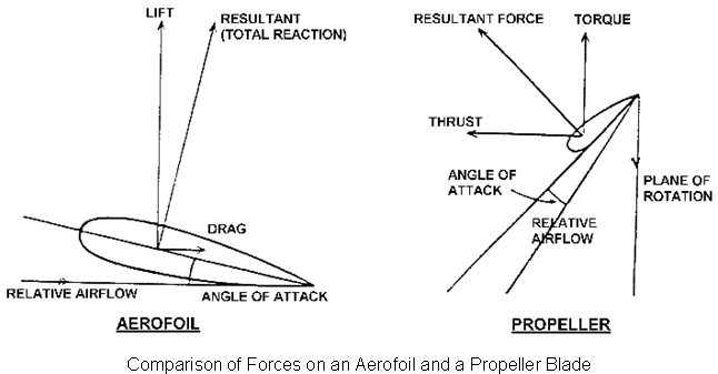
The propeller blade is of Aerofoil section with some changes in terminology and the forces produced as it moves through the air are roughly equivalent to the forces of lift and drag produced by an aircraft wing. These forces are called thrust and torque and are shown in comparison with an aerofoil.
Newton's Second Law states that Force = Mass ´ Acceleration and Thrust being a force, the same expression applies, being equal to the mass of air handled and the speed of the slipstream, less the speed of the aeroplane. Therefore, the power expended in producing thrust depends on the mass of air moved per second. On average, thrust constitutes 80% of the total horsepower absorbed by the propeller (torque). The other 20% is lost in friction and slippage. For any speed of rotation, the horsepower absorbed by the propeller balances the horsepower delivered by the engine.