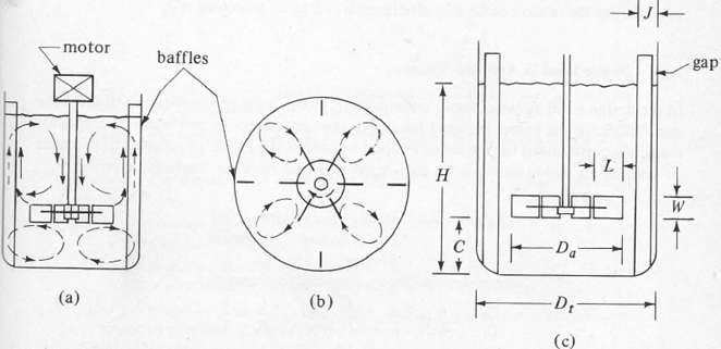
The diagram below shows a baffled tank with a six blade turbine agitator:

FIGURE 1
(a) Is a side view
(b) Is a bottom view
(c) Gives dimensions of the turbine and the tank.
It is important to note the dimensions given and identify them against the definitions you have been given. This tank contains baffles that are fitted to give a more favourable mixing profile. You should be able to identify the following:
Dt is the Tank Diameter
Da is the Turbine Diameter
C is the clearance of the Agitator from the bottom of the tank
W is the is the Turbine Width
L is a Turbine Internal Measurement
H is Liquid Height
J is Baffle Width
Without the baffles a swirling flow pattern develops. For vigorous agitation with vertical agitators baffles can be used to prevent swirling and improve the mixing. Usually 4 baffles are sufficient; their width is usually about 1/12 of the tank diameter. As in the first case study we considered in lectures, sometimes with large liquid depths 2 or 3 impellers are mounted on the same shaft; each acting as a separate mixer. The bottom impeller is usually 1 impeller diameter above the bottom of the tank.
If you use the type of agitator shown in the Figure 1 the geometric proportions are usually taken as:

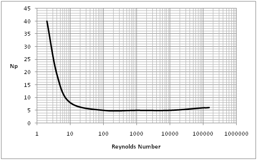
A typical curve for finding the Power Number for the type of impeller described is given below. This curve applies for Da/W = 5, and Dt/J = 12. The Reynolds Number can be calculated using the formula quoted on the 'Scale Up for Tanks' sheet.

This type of tank is used in part of the production of a fine chemical such as aspirin. The first calculation we are required to do is to calculate a typical Power Consumption in the type of agitator and tank given in FIGURE 1. The Tank Diameter is Dt, the Turbine Diameter is Da, Dt = H and the Width is W. The individual values used for these parameters are given on a separate sheet (See below). The tank contains 4 baffles each having a width J. The Turbine is operated at N rpm and the liquid in the tank has a viscosity of mcp and density, r kg/m3.
i. Calculate the required power of the mixer in kW
ii. For the same conditions, except for the liquid having a value of m =100000 cp, calculate the required power and comment on your answer.
NOTE: Viscosity will normally have units of which is Pa s.
1 cp is 1x10⁻³ Pa s. You would normally expect your initial calculated value of the power to be in J/s.
|
Dt(m)
|
Da(m)
|
W(m)
|
J(m)
|
N(rpm)
|
µ(cp)
|
P (kg/m3)
|
z
|
|
|
|
1.75
|
0.61
|
0.122
|
0.146
|
90
|
10
|
930
|
3.5
|
|
|