Air-System in Aircraft Engine:
In the working cycle and airflow section we discussed the main airflow and working cycle of a gas turbine engine and found that a major function of the airflow through the engine was to act as a cooling medium and that only a small proportion of the air was used to support combustion. In fact, because of the intense heat developed, gas turbine engines only became practical power units when it was discovered that the airflow could be used to ‘insulate' the structural materials and thus provide acceptable working temperatures for the materials. Many parts of the engine, made from light alloy or ferrous metals, have to be protected from the very high temperatures. To achieve this, an efficient and effective cooling system is needed and this is provided by ducting cooling air from the main gas stream.

In addition to its function of cooling, the airflow is also used to pressurise oil seals and bearings to prevent oil leakage. We thus have the two functions of cooling and sealing to consider. In general, independent airflow's are taken from the engine compressors to provide:-
• Low pressure for sealing.
• Intermediate pressure air for some cooling functions.
• High-pressure air for the remainder of the cooling functions.
These are considered in the paragraphs that follow.
INTERNAL COOLING AIRFLOW
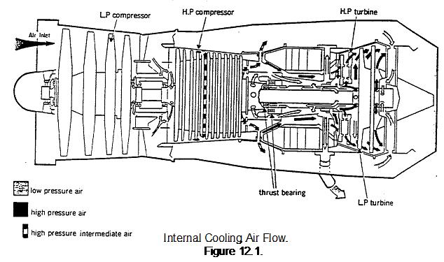
Because of the different design features of different gas turbine engines, the cooling airflow varies considerably from one engine type to another. However, the basic principles remain the same and can be explained by using an example. Figure 12.1. shows the cooling and sealing airflow of a two-spool, low ratio by-pass engine. To show the cooling airflow more clearly, the by-pass and main air-stream air paths have been omitted.
A study of the figure will show that air is supplied from the low-pressure compressor and also from the high-pressure compressor. This gives the range of pressures required, as mentioned in the previous paragraph. After doing its job, the air is either vented directly to atmosphere or fed into the exhaust gas flow.
LOW PRESSURE AIR
Air is taken from the low-pressure compressor outlet and ducted through the engine to become both a sealing and cooling airflow. This airflow:-
• Pressurises the main bearing oil seals to prevent oil leakage.
• Provides cooling for the low-pressure compressor shaft, the front half of the high-pressure compressor shaft and the turbine shaft.
INTERMEDIATE PRESSURE AIR
This airflow is taken from an intermediate stage of the high pressure compressor and passes through transfer ports to cool the rear half of the high pressure compressor shaft and also the rear face of the last disc of the compressor; it then flows outwards through tubes to mix with the by-pass airstream.
HIGH PRESSURE AIR
This airflow is taken from the high-pressure compressor outlet and is ducted to all faces of the turbine discs to maintain the temperature within the required limits. The pressure of the cooling air is greater than that of the hot gases and since the air is directed outwards across the faces of the turbine discs, it prevents the hot exhaust gases flowing inwards across the discs. Overheating of the turbine discs is thus prevented.
DIFFERENTIAL PRESSURE SEALS
We know that we require high pressure cooling air at the turbine discs (to reduce the flow of hot exhaust gases across the discs) and low-pressure air at bearing seals (to prevent leakage of oil without undue aeration of the oil). The air at these different pressures must be prevented from mixing and thus, becoming equalised in pressure. This is done by inserting differential pressure seals at appropriate points in the system; these seals are of a multi-groove rotating type.