Reference no: EM13920477
Part I: Hardware Software Co-deign
Task 1- Write the specification of LOAD MOVER (detailed of the whole design and precise for automatic control section).
Requirement:
1. It should be able to move 35 kgs.
2. It can be operated wirelessly, manually and automatically.
3. It can detect hindrances and take decision to avoid them.
4. It can store a map of 2 x 3 points to move on automatically.(A, B, C, D, E, F)
5. Map can be updated by serial port.
6. It can take snap of each load and store it in SD card.
7. It can climb a slope of 4 feet.
8. The weight panel should be around 1.5 x 3 feet.
9. It can talk to the customer and respond to fixed five questions.
10. It should run on battery (battery charger).
11. Decide the Processor/ASIC/ASIP/SOC/FPGA.
12. Divide the design into various modules.
13. Is the kernel required if yes which one?
14. Does the project has real time features.
15. Which class of SOC is suitable?
16. What memories are required? (SRAM/SDRAM/FLASH/EEPROM)
17. What does be the size of the memories?
18. Engine control section
19. Wireless control section
20. Automatic control section
21. Weight sensor and Infrared sensor
22. Camera interface
23. Card reader section
24. Audio interfacing section
25. Battery charger section
26. Write the specification document for each section per group.
Task 2- (Everyone should use simulinkmatlab2011)
Design the Automatic control section using Statecharts using Stateflow and Simelectronics tool box.
Automatic Control System-
Objective: The aim of this project is to design an embedded system which can move loads from one place to another. The system can be operated manually, automatically and wirelessly.
Rough Specification:
1. Maximum Weight: Maximum load on the system should not exceed 35 kg.
2. Maximum speed: of the system should not be more than 10kmph
3. 90 degree turns: It can make 90 degree turns easily
4. Inclination of slope: must be less than 25 degrees.
5. The system has to detect any obstacle in its path and should stop in advance of 50cm.
6. Dimensions: The dimension of the system is 60cmx60cm.
7. There shouldn't be any link to off-board computers.
8. The vehicle can use on-board memory to its advantage.
Task 3- Write a System C/C++ program for Bus Arbiter
The bus arbiter is a device used in multi-master system with shared bus. It is used to allocate the control of the shared system bus to one master at a time depending priority. The device can support three bus masters and three slaves. It can accept bus request signals from bus masters and depending on the priority it can give bus grant signal to one of the master. The device has fixed priority. Each transfer takes five cycles at a time one master and slave communication occurs.
Part II: Reconfigurable Computing
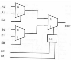
Question 1. Implement the following function using Actel ACT-1 logic block. Complemented inputs are not available. F(a,b,c)= ∑(0,1,3,4,6,7);

Question 2. Implement the Boolean function given below using minimum number of function generators (F, G) of XC2000. Draw the K-maps for the function and write the expression.
F (a, b, c, d, e) = ∑(0, 5, 6, 9, 12, 17, 19 ,21, 27 30, 31)
Show the implementation in CLBs and mention the mode used. The implementation should be truly combinational.
Question 3. Draw the PLA programming table for the following function using a PLA of a minimum size. F1(X,Y,Z)=Σ(1,4,5,7) F2(X,Y,Z)=Σ(0,2,5,6)
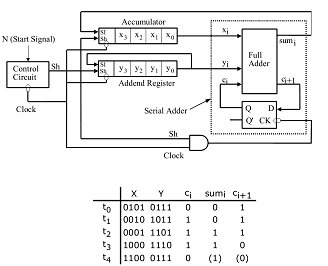
Question 4. Write the verilog code for the serial adder element given below:

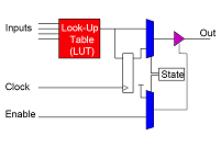
Question 5. Write the verilog code for Logic element unit given below:

Part III: NETWORK EMBEDDED APPLICATION
Question 1. Select a route by using LD, LC, DCUR heuristic and RDM heuristic for a call R whose specifications are R =(1,A,F, B,12) . Cost and delay values are specified in the brackets for the respective links. Compare the results. Assume that the call satisfies the bandwidth test

Question 2.a) An incomplete VTCSMA-L transmission status table for ? = 2 and transmission time equal to 20 is given below. Find how many calls can be sent and at what time?
|
Node
|
RC at arrival
|
DM
|
LM
|
RC at Transmission
|
|
1
|
2
|
28
|
8
|
|
|
2
|
10
|
40
|
20
|
|
|
3
|
12
|
56
|
36
|
|
|
4
|
18
|
68
|
48
|
|
|
5
|
24
|
86
|
66
|
|
|
6
|
40
|
102
|
82
|
|
b) Show the working of LDCR and MDCR protocol on the given message set.
For nodes Ni (arrival, slots, deadline) :{(4,3,30), (2,2,6), (0,1,2), (3,4,7), (5,4,16), (16,3,23)}
Question 3.a) A set of six tasks with backup copies is to be scheduled by using Myopic algorithm with some distance. Find that distance with which the tasks are feasibly scheduled. Draw schedule also.
|
Task
Ti
|
ri
|
di
|
ci
|
|
T1
|
0
|
20
|
6
|
|
T2
|
0
|
25
|
8
|
|
T3
|
4
|
30
|
5
|
|
T4
|
6
|
40
|
5
|
|
T5
|
8
|
50
|
4
|
|
T6
|
8
|
50
|
6
|
b) If the set of tasks given in Q 3 a) is scheduled on three processors using The Backup Overloading Algorithm, how much time do you save?
Part IV: REAL TIME SYSTEMS
Question 1. Answer following questions in short and to the point only.
(a) What are the strategies, kernel chooses for handling aperiodic and sporadic jobs?
(b) What are the advantages of modular programming in RTS?
(c) How redundancies are provided in preventive type of fault-tolerant systems?
(d) Discuss in short, advantages and disadvantages of static and dynamic memory allocation.
(e) Why semaphores are important in RTOS?
Question 2. A system of four tasks T1 = (4,1), T2 = (10,2), T3 = (12,2) T4 = (30,3) is scheduled with executive cyclic clock driven scheduling algorithm. A stream of sporadic jobs arrives as follows, Si = {(2,2,16) ;(18,4,32); (18,3,28)}
(a) Schedule these sporadic jobs applying acceptance test.
(b) Draw neat schedule up to 10 frames showing accepted sporadic jobs scheduled.
Question 3. A system of five periodic tasks Ti {(5, 1); (7, 1); (8, 1); (12, 1.5); (25, 4)} is found to be schedulable using RMA. Now find out the maximum value of context switch 'CS', such that the system remains schedulable.
Question 4. A set of hard real-time periodic tasks need to be scheduled using RMA. The following table contains the details of these tasks and their use of shared resources. Can all the tasks meet their respective deadlines when priority ceiling protocol is used for resource scheduling?
|
Task
|
Pi
|
ei
|
R1
|
R2
|
R3
|
R4
|
R5
|
|
T1
|
50
|
15
|
6
|
7
|
--
|
10
|
3
|
|
T2
|
100
|
25
|
--
|
--
|
--
|
8
|
--
|
|
T3
|
150
|
40
|
4
|
14
|
8
|
--
|
10
|
|
T4
|
200
|
35
|
--
|
--
|
--
|
--
|
--
|
|
T5
|
250
|
50
|
6
|
11
|
--
|
9
|
7
|
Question 5. Use Petri Net for 2x2 matrix multiplication. Write all the places and transitions clearly. Write firing table also.
Part V: Digital Signal Processing
Question 1. Design a digital Chebyshev-II filter that satisfies the following constraints
0.7 ≤ |H(ω)| ≤ 1, for 0 ≤ ω ≤ 0.2π
|H(ω)| ≤ 0.2, for 0.6π ≤ ω ≤ π
Use Impulse Invariant transformation and verify the design. T=1.
Question 2. The frequency response of an FIR filter is given by
H(ω) = e-3jω (1+1.8cos3ω+1.2cos2ω+0.5cosω)
Determine the coefficients of the impulse response h(n) of the FIR filter.
Question 3. An FIR bandpass filter is to be designed to meet the following frequency response specifications:
Passband : 0.30-0.50 (normalized)
Transition width : 0.05 (normalized)
Stopband Deviation : 0.02
Passband Deviation : 0.01
(i) Sketch the tolerance scheme for the filter.
(ii) Express the filter bandedge frequencies, assuming a sampling frequency of 5KHz and the stopband and passband deviations in decibels.
Question 4. Explain the various FIR Filter design methods.
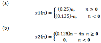
Question 5. Determine the Z-transforms and sketch the ROC of the following signals.

(c) x3(n) = x1(n-4)
(d) x4(n) = x1(-2n)
Question 6. Compute the eight-point DFT of the sequence

Using the radix-2 decimation-in time and decimation-in frequency algorithms.
Question 7. Perform the circular convolution of the following two sequences x1(n) = {1,2,3,4} x2(n) = {5,6,7,8} using DFT - IDFT method.
Question 8. Consider an FIR lattice filter with coefficients K1=0.5, K2= -0.45, K3=0.6.
(a) Find its impulse response by tracing a unit impulse input through the lattice structure
(b) Draw the equivalent direct form structure.
Question 9. An analog signal xa(t) is band limited to the range 150 ≤ F ≤ 750 Hz. It is used as an input to the system shown in fig below. In this system, H(w) is an ideal low pass filter with cutoff frequency Fc =250 Hz. Determine and sketch the spectra for the signal x(n), w(n), v(n) and y(n).

Question 10. Consider the two different ways of considering a decimator with an interpolator shown in fig.

(a) Show that the outputs of the two configurations are different. Conclude the result.
(b) For what values of D and I, the systems are identical in general.
Question 11- Prove the equivalence of the two decimator and interpolator configurations shown in fig.

Question 12. Discuss briefly on each of the following concepts using diagrams.
(a) SHARC Architecture
(b) Pipelining and parallel processing
(c) MAC Unit
(d) Special instructions
(e) Data and program memory
Question 13. Consider linear prediction in noisy environment. Suppose that a signal d(n) is corrupted by noise x(n) = d(n)+w(n), where rw(k) = 0.25δ(k) and rdw(k) = 0. The signal d(n) is an AR(1) process that satisfies the difference equation d(n) = 0.25d(n-1)+v(n), where v(n) is the white noise with variance =1. Assume that w(n) and v(n) are uncorrelated.
(a) Design a first-order FIR linear predictor w(z) = w(0)+w(1)z-1 for d(n) and find the mean square error ξ = E{[d(n+1) - d(n+1)2]}.