Reference no: EM131475149
Topic: Dynamics and Controls
[1] Reduce the block diagram given in Fig. 2 and find the transfer function from X(s) to Y(s).
Bonus: Compute the transfer function from X(s) to E(s)

[2] The mast in Fig. 3 rotates around point O. Ignore the pulley's friction and mass.
(a) Write the equations of motion of the mast (Output = θ, Input=F) in terms of the parameters shown on the graph ONLY.
(b) Linearize the equation(s) around equilibrium point(s).
(c) Find the transfer function representing the mast angle (θ) as a function of the motor pulling force (F).
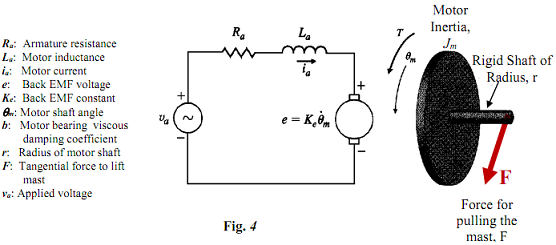
[3] Consider the motor used to raise the mast in Problem 3. The cable force F is tangential to the shaft of the motor. The motor bearing has viscous damping coefficient b. The schematic diagram of the motor electrical and mechanical components is shown in Fig. 4. The rotation of the motor is designated by θm and the current in the motor winding is designated by ia. The applied voltage to the motor is va. Write the equations for the motor dynamics using the parameters shown on the Fig. 4 ONLY.
Bonus: Write the state space equations of the system.
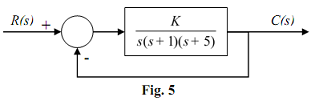
[4] (a) Draw the line magnitude plot of the system shown in Fig. 5 for K=10 (use provided graph sheet).
(b) For which value(s) of K the system is unstable.
Bonus: Draw the magnitude plot for K=100 (1 point. No credit is given if the magnitude plot is drawn following the same steps as in (a)).

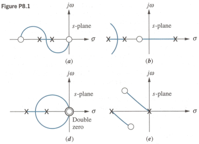
[5] For each of the root loci shown in Fig. 6, tell whether or not the sketch can be a root locus. If the sketch cannot be a root locus, explain why. List all reasons on the graph itself.
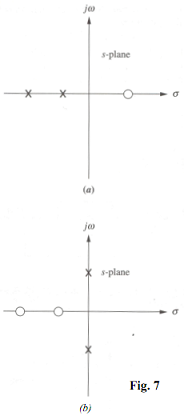
[6] Sketch the general shape of the root locus for each of the open-loop pole-zero plots shown in Fig. 7.
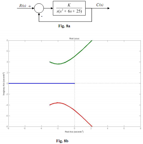
[7] The root locus for the system shown in Fig. 8a is shown in Fig 8b. (a) Using the root locus, find the complex poles which will lead to the closed-loop system having a natural frequency equal to ωn= 4.0 rad/s and a damping ratio ζ = 0.36. (b) What is the value of K for your choice?
[8] What type of controller C(s) will lead to perfect tracking of unit step input for the system in Fig. 9? P or PI? Explain why.

Bonus:
What is gain margin? What is phase margin?
How do you choose P, I, or D or a combination of these to use for controlling your system?
What is Routh Hurwitz array and what is it used for?
Can you state one problem with the Routh Hurwitz method?
What is aliasing?
What is Nyquist Frequency?
State one advantage and one disadvantage of open-loop control.
State one advantage and one disadvantage of Closed-loop control.
Why do you need to linearize a system?
How do you linearize a system?
[9] A linear model of a DC motor is shown in the figure below. The definitions of the system parameters and variables are as follows:
θm: motor-rotor rotational displacement
Jm: motor-rotor inertia
Bm: motor viscous-damping coefficient
va: armature voltage
ia: armature current
Ra: armature resistance
La: armature inductance
vbemf: back emf voltage
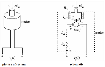
a) Write the governing differential equations of the system. In this linear model, you may assume that the motor's back end constant is equal to its torque constant (kbemf = kt).
b) Consider that there are an input va()t and an output θm (t) in the system. Derive the transfer function from the input to the output.
[10] You may consider this a continuation of the previous problem. With a given set of parameters, a DC motor transfer function can be written as 0.2/(s2 + 0.4s + 0.8).

a) Can a PD controller D(s) = kp+ kds make the steady-state error to a unit step input be zero? If so, prove it. If not, find the steady-state error to a unit step input (as a function of kp and kd).
b) Design a PD controller D(s) = kp + kds that satisfies the following closed-loop transient specifications: ts < 4.6 s and tr < 1.8 s. Neglect the effect of additional zeros.
c) Can a PID controller D(s)= kp + kis-1 + kds make the steady-state error to a unit step be zero? If so, prove it. If not, find the steady-state error to a unit step input (as a function of kp, ki, and kd).
[11] Fig. 3 shows a typical control system block diagram. The plant transfer function is given by

G(s) = 1/s(s+10)(s+1000)
(a) Sketch the root locus for K > 0. Calculate the approximate location of the breakaway pole by neglecting the open-loop pole at s = -1000. You do not need to calculate the jω-axis crossing point.
(b) Show that the proportional controller K cannot make the closed-loop system satisfy the following performance criteria.
- The step response has a settling time Ts ≤ 0.575 sec. (Ts = 4.6/σ for 1% criterion).
- All closed-loop poles have a damping ratio ζ ≥ 0.707.
[12] The system described by the following block diagram must be designed so that its closed-loop poles are placed within the shaded regions as shown in the diagram given below.

a) Determine the range of values the natural frequency and the damping coefficient could take for the closed loop poles to lie in the shaded region, where θ1 = 32o, θ2 = 29o.
b) For the closed loop poles to be in the shaded region, determine the range of the constant, 'k'.
c) For ωn = 50; ζ = 0.67, what are the values of the constant, ' k1' and 'k'?
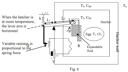
[13] The following figure shows a simple model of an automatic egg hatcher. The egg has a temperature of T1 and being heated in the hatcher by an electric heater supplying heat at the rate Qi(t). Qi(t) is supplied by a resistance R as shown in the figure. A temperature control system is used in the hatcher to control the amount of heat going into the system. The angle θ of the lever of the controller is proportional to the temperature T2 (constant of proportionality is α). The heat extraction variable resistor is proportional to the force in the spring k (constant of proportionality is β). The temperature inside the hatcher is T2, the walls are at temperature T3 and the ambient temperature is Ta. The thermal capacitances of the egg, the air inside the hatcher and the hatcher walls are Ch1, Ch2 and Ch3 respectively. Assume small angles and mass less lever.
(a) Derive the equations of motion for this system assuming that the heat is transferred by conduction inside the hatcher and by convection outside it (convective heat transfer coefficients at the wall is hc3). Use variables shown on the diagram only.
(b) Derive the state-space equations assuming temperature T1 and T3 as the outputs.
[14] (a) Complete the magnitude plot of the open-loop system given by:
G(s)H(s) = (100s+7000)/(s3 + 34s2 + 320s + 800)
(The phase plot is already drawn for you)
(a) Determine the phase and gain margins of the system.
(b) If an input u(t)=10sin(10t+π/2) is applied to the open loop,

what will be the steady state y(t)?
Attachment:- Assignment File.rar