Reference no: EM132194609
Problem 1
Consider the following circuit. Assume Vγ = 0.7V, R1 = 1kΩ, R2 = 1kΩ, VDC = 2V.
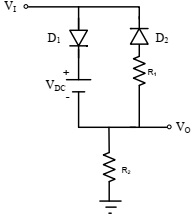
Plot VO versus V1 for -5V < V1 < 5V.
Problem 2
Consider the following circuit with R1 = 40kΩ, R2 = 60kΩ, RL = 5kΩ, RE = 1kΩ, RS = 4kΩ, β = 100, VA = 100V, VBE(ON) = 0.7V, VT = 0.026V.
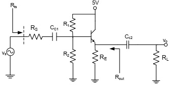
a) Determine the Q-point (IC, VCE)
b) Draw the small-signal equivalent circuit and determine Ris and Rout
c) Determine the voltage gain.
d) Draw the dc and ac load lines and determine the maximum symmetrical output voltage swing.
Problem 3
Consider the following circuit. VDD = 15V, R1 = 600kΩ, R2 = 400kΩ, RL = 20kΩ, RD = 2.5kΩ, RS1 = 100Ω, RS2 = 900Ω, Kn = 1mA/V2, VTN = 1.5V, λ = 0.
a) Determine the Q-point.
b) Draw the small signal equivalent circuit.
c) Determine the voltage gain.
d) Determine Rin and Rout
Problem 4
Consider the following circuit. Assume VTN = 1.0 V, Kn = 1 mA/V2, λ = 0, V+ = 5V, V- = -5V, RL = 5kΩ, RSi = 5kΩ, RG = 600 kΩ.
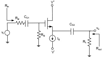
a) Draw the small signal equivalent circuit
b) Write the expression for the voltage gain.
c) Determine IQ such that Av = 0.9
d) Determine Rin and Rout
e) Determine VDS and VGS.
Extra Credit
Consider the following circuit. Assume Vγ = 0.7V, VB = 3V. Assume the RC time constant to be much larger than the period of the input signal.
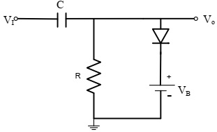
Plot the steady-state Vo as a function of time for VI = 10 sin (1000t) V.