Reference no: EM132536160
Circuit Simulation Assignment
With circuit simulation of your choice, do the following problems:
Question 1. For the circuits in Figure P1, each utilizing diodes of the 1N4149 type (.model D1N4148 D (Is=0.1pA Rs=16 CJO=2p Tt=12n Bv=100 Ibv=0.1p), plot the output waveform of the circuit for a 10V peak amplitude input sin wave having a frequency of 1 kHz.
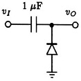
(a)
(b)
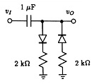
(c)
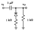
(d)
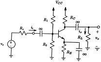
Question 2. For the common-emitter amplifier shown in Figure P2, let Vcc = 9V, R1 = 27kΩ, R2 = 15kΩ, RE = 1.2 kΩ, and RC= 2.2 kΩ. The transistor has ß = 100 and VA = 100 V. Using Spice, calculate the DC bias current IE. If the amplifier operates between a source for which RS = 10kΩ and a load of 2 kΩ, determine the values of input impedance, Rin, gm, output impedance, Ro and voltage gain, Av.
Question 3. Do problem 6.60 (simulation) from the textbook
Submit the following:
1. Title page with your name, course number, course title, date submitted, department and university name
2. Schematic or text file of your simulated circuits using any simulation software (Multisim, LTSpice, etc).
3. Input file and probe output. Write relevant values on the probe waveforms with the help cursor which is an option in the simulation program.
4. ALL required findings.
5. All required waveforms.
Attachment:- Electronics-Simulation Assignment.rar