Reference no: EM132362052
Programming with MATLAB Project -
Introduction - Four-bar linkages are used in a variety of common mechanisms such as the windshield wipers on many cars. A four-bar linkage is shown in Fig. 1 [1].
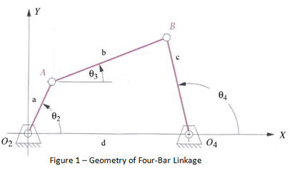
The line connecting points O2 and O4 in the figure is fixed, so it acts as a link, hence the name "four-bar linkage." In this project, the motion of a four-bar linkage will be animated. Link a will rotate counterclockwise about node O2 at a uniform rate and the motion of links b and c will be computed.
Geometry - In Fig. 1, the links are labeled a, b, c, and d. Each node has a label, with the nodes that are fixed in space labeled O2 and O4, and the nodes that move labeled A and B. The angles that links a, b, and c make with the x axis are labeled θ2, θ3, and θ4 respectively.
Equations - As shown in Fig. 1, the x, y coordinate system has its origin at node O2. At any given angle θ2, the x and y coordinates of nodes A and B are required. Letting a, b, c, and d represent the lengths of the four links, the coordinates of A and B can be calculated using the following equations (see attached file).
Plots - The general idea is to create a loop over a series of values of θ2. For each angle, calculate the coordinates of nodes A and B. Once the coordinates are known, draw straight lines from node O2 to A, from A to B, and from B to O4.
Recipe -
1. Write a function with 6 inputs and no outputs. The inputs will be
a. Length of link a
b. Length of link b
c. Length of link c
d. Length of link d
e. Number of revolutions of link a
f. Number of steps taken in each revolution
2. Create a vector containing the values of θ2 required for the simulation. It will depend on the 5th and 6th inputs to the function. The angles can be in either radians or degrees, making sure you use the correct MATLAB functions for whichever you choose. Note that there are 2π radians or 360o per revolution.
3. Set the x and y coordinates of the fixed nodes O2 and O4.
4. Some sets of specified link lengths will work and others will not, depending on whether the radical (argument of square root) in Eq. (8) is positive or negative. Check the value of the expression Q2 - 4PR. If it's positive, the linkage will work. If not, print an error message and return from the function.
5. Calculate the initial x, y coordinates of nodes A and B corresponding to the first value in the vector from step 2.
6. Plot lines connecting O2 to A, A to B, and B to O4. Make sure you save the plot handle(s) as we did in the pendulum example.
7. As in the pendulum animation we did in class, the axes should have equal increments and the axis limits should be fixed. Note that the axis limits, which can be set with the axis function, will depend on the input link lengths. The following limits seem to work well:
axis equal
axis([ -0.5*d, 1.5*d, -0.5*d, 1.0*d])
8. Create a loop to loop over the remaining values in the vector from step 2.
9. For the current value of the θ2 vector (from step 2), calculate the new coordinates of A and B. Make sure you do the test described in step 4 since the value of the radical will be changing.
10. Change the values of XData and YData in the plot handles based on the new coordinates to plot the new positions of the links.
11. Add drawnow to the end of the loop to make sure MATLAB doesn't buffer the data.
12. Test the program using the following inputs:
a. Length of link a = 4
b. Length of link b = 24
c. Length of link c = 14
d. Length of link d = 30
e. Number of revolutions of link a = 3
f. Number of steps taken in each revolution = 101
13. If the animation runs too fast you can add a call to the pause function at the end of the loop.
References - Norton, R. L., "Design of Machinery," 4th ed., McGraw-Hill, 2008.
Attachment:- MATLAB Final Project.rar