Reference no: EM131522243
Lab Activity Assignment 1: Multisim- Voltage Dividers
Procedure:
Open Multisim Software
Program Files -> National Instruments (folder) -> Circuit Design Suite -> Multisim
START A NEW PROJECT BY GOING TO FILE>NEW>NI ELVIS I Design. You will get a workspace that has the connections you will find on our ELVIS board. Later we will see a 3-D Model of the ELVIS Board.
Part 1:Build a Voltage Divider and Test it with Loads.
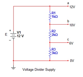
Construct a voltage dividerwith a 12V source and use 1000, 2000 and 3000 Ohms to divide the voltage into 10V and 6V at nodes in the circuit.Va, Vb, Vcare the connection points you will use to load to the circuit at 12, 10 and 6V. You will want to put voltage indicators on each one connected between ground and each test point. This will save you time when you put the load on the circuit, to see the voltage change at the connection point when you add a load. To get the 12 V source, can go to Simulate > Instruments >NI ELVIS mx instruments > NI ElVIS Variable Power Supply just like you would see in the ELVIS Instrument panel. But to simplify this circuit INSTEAD USE DC POWER SUPPLY FOR 12V SO YOU HAVE A BATTERY ON THE BOARD. This will make the 3-D circuit construction easier later.
Insert the image of your voltage divider circuit here. It does not need the extra labels that mine has, but make sure the voltage indicators are included and show that you have the correct voltages. Do NOT have a load resistor yet on this circuit:
To load the circuit you will place one resistor between ground and either Va, Vb or Vc. You will only have one load resistor on the circuit at any one time, unused connection points remain unattached!!!
You can use Excel to do the calculations to save time filling in the chart.
|
Location to measure Voltage
|
Load Resistor connected at that location
|
Expected voltage (with no load)
|
Measured voltage (with specified load)
|
% difference (Difference divided by expected)
|
Power delivered to load resistor using measured voltage. P = (V^2)/R
|
|
Vc
|
1kOhm
|
6 V
|
|
|
|
|
Vc
|
4.7kOhm
|
6 V
|
|
|
|
|
Vc
|
10kOhm
|
6 V
|
|
|
|
|
Vc
|
20kOhm
|
6 V
|
|
|
|
|
Vc
|
100 kOhm
|
6 V
|
|
|
|
|
Vb
|
1kOhm
|
10 V
|
|
|
|
|
Vb
|
4.7 kOhm
|
10 V
|
|
|
|
|
Vb
|
10 kOhm
|
10 V
|
|
|
|
|
Vb
|
20 kOhm
|
10 V
|
|
|
|
|
Vb
|
100 kOhm
|
10 V
|
|
|
|
|
Va
|
1kOhm
|
12 V
|
|
|
|
|
Va
|
4.7 kOhm
|
12 V
|
|
|
|
|
Va
|
10 kOhm
|
12 V
|
|
|
|
|
Va
|
20 kOhm
|
12 V
|
|
|
|
|
Va
|
100 kOhm
|
12 V
|
|
|
|
Which load affected the voltage divider the most (highest % difference)? Why?
Which load value resulted in the highest power dissipated in the load resistor at Va? Why?
Which load value resulted in the highest power dissipated in the load resistor at Vb?
Which load value resulted in the highest power dissipated in the load resistor at Vc?
Is it the same load resistor for max power transfer for Vb and Vc?
We will eventually learn how to calculate the load resistance that allows maximum power transfer. But for now, you should see that if the battery is not controlling the voltage directly, adding a load to a voltage divider changes the circuit, and each connection point in the voltage divider has a different load resistance value for maximum power transfer.
USE EXCEL TO MAKE A GRAPH OF THE DATA IN YOU COLLECTED THAT MEETS THE FOLLOWING CRITERIA:
• Your graph should be a scatter plot and show measuredvoltage on the Y axis and Load Resistance on the X Axis
• Each axis is labeled and shows the units.
• The graph should have 3 lines on it, representing the measured values at Va, Vb and Vc at the different load resistances.
• Have a legend so that each line has its own color and is clearly labeledVa, Vb, Vc.
• Have your Name, Date and ENGR 2140 in the title of the graph.
• If you don't know how to make a graph in excel, use this reference. I recommend Scatter Chart as a simple example. You can look up others.
• PASTE THE GRAPH HERE:
Part 2. Building a virtual circuit on a breadboard.
Remember how the holes in the board are connected as you build the circuit (as seen below). THE ENDS OF A 2-TERMINAL COMPONENT SHOULD NEVER BE CONNECTED TOGETHER, YOU JUST BYPASSED IT AND MAY HURT YOUR CIRCUIT OR DEVICES.
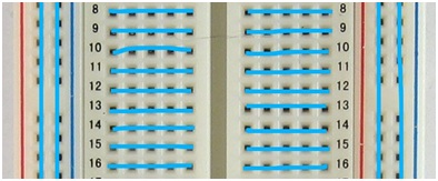
A VOLTAGE SHOULD NEVER BE CONNECTED DIRECTLY TO GROUND!!!
Take your voltage divider circuit and put it in a configuration with a 1.5 kOhm load resistor attached to Vc as your load. Remove all multimeters and indicators from your circuit.Look for an option at the center top of the program to construct a breadboard layout of your circuit (it will be an icon that looks like a breadboard and say "view breadboard" when you hover over it. Selecting it will give you a 3D breadboard and the parts you need to populate your board. Add the components to the breadboard and include wires by clicking on blank holes to add any additional connections. The battery can be placed anywhere, but it is recommended that you connect the positive side to the red bus and the negative side to the blue bus. On some boards the busses break in the middle of the board. You need to add jumpers to activate the full bus if this happens (with standard bread board, but not ELVIS). When you hover over a point to place connector, green squares will appear to show you the other connection points for that hole. Once you have placed everything on the board, go to Tools and select "DRC and Connectivity check" this will tell you if you have any errors. Check to make sure your resistors are in the right order. Pay attention to device names and the order to be error free. The breadboard must be exactly like your diagram to be error free. Pay close attention to every detail, component name and connection. Also make sure you connect your circuit to the board's ground.
TAKE A SCREENSHOT OF YOUR completed 3-D BREADBOARD CIRCUIT AND ATTACH HERE:

(Make sure I can see at the bottom the display that says "Design Rule Check - 0 Design Rule Errors Found" so I know you did it correctly)
When done, submit this assignment in Blackboard, in the Labs folder.
Lab Activity Assignemnt 2: Multisim
Procedure:
Open Multisim Software
Program Files -> National Instruments (folder) -> Circuit Design Suite -> Multisim
Superposition
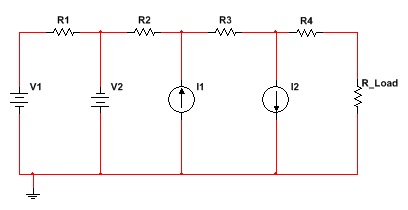
• Make a circuit as shown with two voltage sources and two current sources and five resistors. Choose Voltages between 1 and 12 Volts, Currents between 1 and 12 milliAmperes (mA) and Resistances between 1 kOhm and 100 kOhm. All source values will be positive, but you must match the direction for the components so that you have one in each direction.
• Record the values chosen in the table below. Assume Voltage and Current sources are ideal and have no internal resistance; Multisim will do this as a default.
• With all sources active, measure the voltage across each resistor and the current through each resistor (you will need two indicators or multimeters for each resistor or 10 measurement devices total).
YOU MAY LOSE POINTS ON THE LAB REPORT IF YOU DO NOT SHOW THE INSTRUCTOR THAT YOU HAVE COMPLETED THE LAB UP TO THIS POINT BEFORE YOU LEAVE THE CLASSROOM.
• Then, follow the rules for superposition and evaluate the circuit with only one source in it at a time. This means replacing unwanted batteries with wires and making current sources into open circuits. Start with only E1 and fill in the table. You will have to make a new circuit for every source, which only contains one active source. Make sure you save a picture of each circuit with only one source, as well as a picture with all sources. There is a place at the end of the lab to paste each picture.
Table 1 Circuit Component Values: Insert Chosen Values Here
|
|
E1 (V)
|
E2 (V)
|
I1 (mA)
|
I2 (mA)
|
R1 (k?)
|
R2 (k?)
|
R3 (k?)
|
R4 (k?)
|
RLoad (k?)
|
|
Values Chosen
|
|
|
|
|
|
|
|
|
|
Table 2 Superposition Data, PAY ATTENTION TO DIRECTION (+/-)
|
|
Voltage
|
Current
|
Did you save a picture?
|
|
|
R1
|
R2
|
R3
|
R4
|
RLoad
|
R1
|
R2
|
R3
|
R4
|
RLoad
|
|
All Sources
|
|
|
|
|
|
|
|
|
|
|
|
|
E1 Only
|
|
|
|
|
|
|
|
|
|
|
|
|
E2 Only
|
|
|
|
|
|
|
|
|
|
|
|
|
I1 Only
|
|
|
|
|
|
|
|
|
|
|
|
|
I2 Only
|
|
|
|
|
|
|
|
|
|
|
|
Describe how you would experimentally measure the Thevenin Eth and Rth values for this circuit and save a picture of the measurement for Eth and Rth.
Description of process:
Eth value:
Rth value:
Questions.
1. In your own words, explain superposition.
2. How does the data in the table support the superposition Theorem? (Hint: If you measured correctly, in each column of Table 2, the sum of the data in rows 2, 3, 4, and 5 should equal the value of the data in row 1. If it does not, you may want to check your circuit and correct the measurements.)
Insert 7 Circuit Pictures here with YOUR NAME AND DATE VISIBLE ON THE CIRCUIT.
1. All Sources
2. E1 Only
3. E2 Only
4. I1 Only
5. I2 Only
6. Eth being measured
7. Rth being measured.
Attachment:- Scatter Chart.rar