Reference no: EM132505804
ELEC 10004 Electronic Circuits Assignment - Middle East College, Oman
Module Learning Outcomes - The following LOs are achieved by the student by completing the assignment successfully
1. Classify various applications of pn-junction diode.
2. Indicate the BJT biasing circuits.
3. Show the different FET biasing circuits.
Assignment Objective -
1. Study in details about diode and analyse diode circuit.
2. Know transistor working and types.
Assignment Tasks -
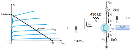
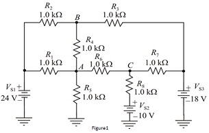
Q1. a. For the emitter bias network of Figure 1, Determine the IB, VCE, VC, VE, VB and VBE.
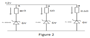
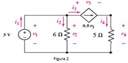
b. Find the branch current for the circuit shown in figure 2.
Q2. a. Can an ordinary diode be used as a Zener diode? Justify your answer.
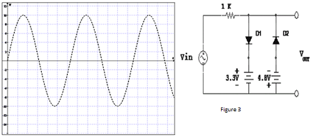
b. As shown in Figure 3,
i. Explain and determine Vout for the given network.
ii. List the applications of clipper circuit.
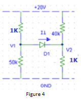
Q3. Assume the diode is Si, find the diode voltage (VD) and (ID) using the constant voltage drop model. For the circuit diagram given in Figure 4.
Q4. a. A Si diode carries a current of 13mA when a forward bias of 4V is applied at (20oC). k = 1.38 x 10⁻²³, q = 1.6 x 10⁻¹⁹, Find the following:
i. The reverse saturation current.
ii. The bias voltages required for diode currents of 10 mA.
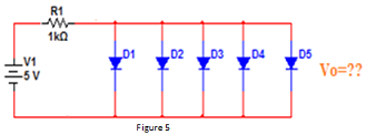
b. Find the total current (IT) and Vo as shown in Figure 5 (assume all the diodes are silicon).
c. Explain Pinch-off voltage for a JFET transistor with the help of a neat diagram.
ELEC 10003 DC Electrical Circuit Analysis Assignment - Middle East College, Oman
Module Learning Outcomes - The following LOs are achieved by the student by completing the assignment successfully
1. Describe the concepts of voltage, current and resistance for simple dc circuits.
2. Apply nodal analysis techniques in analyzing dc electrical circuits.
Assignment Objective - To study and apply various analysis techniques to solve DC electrical circuits.
Assignment Tasks -
Q1. In the circuit shown in Figure 1, use the nodal analysis to find the voltage at node A ,B and C with respect to ground.
Q2. a. The power generated in a resistor is 2 W. What would be the power generated if the current through the resistor is doubled and the resistance remains unchanged.
b. For the circuit in Figure 2,
i. Calculate the voltage and current through all the four elements and
ii. Calculate the power absorbed by all the four elements.
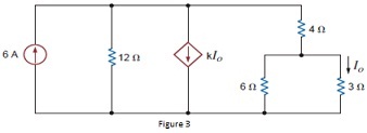
Q3. a. Find the value of K in the network in Figure 3, such that the power supplied by 6A the source is 108 W.
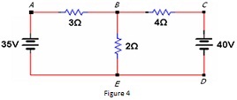
b. For the given circuit in Figure 4, determine the following:
i. The number of nodes.
ii. The number of branches.
iii. If we move from A to B to E to D to C to B, have we formed a path? A loop?
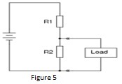
Q4. a. For the circuit shown in Figure 5, what will happen to the voltages across resistors R1 and R2 when a load resistance is connected across R2?
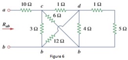
b. Calculate the equivalent resistance Rab in the circuit Figure 6.
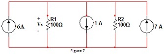
c. Find the value of voltage Vx in the circuit given in Figure 7.