Reference no: EM131089883
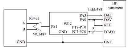
The objective of this exercise is to design a microcomputer-based IEEE488 to RS422 simplex converter (Figure 14.23). Your single-chip microcomputer system will perform handshaked parallel input from a IEEE488 output device, buffer it in an internal FIFO, then transmit the data on an asynchronous RS422 simplex serial channel. The serial protocol is 8-bit data, one stop, no parity, and 300 bits/s baud rate. The input bandwidth can vary from 0 to 1000 bytes/s, with an average of 10 bytes/s. The internal FIFO will allow temporarily the input bandwidth to exceed the output bandwidth. The IEEE488 sequence of events to transmit 1 byte is:
1. Your microcomputer signals it is ready for the next data by making RFD = 1;
2. Eventually the IEEE488 output device will provide the 8-bit data and make = 0;
3. Your microcomputer makes RFD = 0;
4. Your microcomputer should read the data, put it into the FIFO, then make = 1;
5. Eventually the IEEE488 output device will make = 1 and remove the data;
6. Your microcomputer makes DAC = 0.
Figure 14.23

We can simplify this dedicated interface by connecting the to RFD, skipping Steps 1 and 3:
2. Eventually the IEEE488 output device will provide the 8-bit data and make = 0;
4. Your microcomputer should read the data, put it into the FIFO, then make DAC = 1;
5. Eventually the IEEE488 output device will make = 1 and remove the data;
6. Your microcomputer makes DAC = 0.
a) What should your microcomputer do when the FIFO is full? Why?
b) Show all the software including the interrupt handlers, rituals, main program, reset vector, interrupt vector, and ORG statements that place the code into the appropriate addresses on the single-chip microcomputer. You may use a FIFO without showing its implementation if you explain where in memory the data, pointers, and subroutines reside.