Reference no: EM132764596
HS1011 Data Communication and Networks - Holmes Institute
Assessment - Critical Thinking & Topics Research
LO 1: Understand the concepts and principles of technology related to electronic data communications and computer networking for information systems.
LO 2: Demonstrate an understanding of the terminology of network communications technology, network operating systems and network applications and appreciate the need for different types of networks
LO 3: Define, prioritise and evaluate the requirement of the business to provide data communication and networking requirements.
Purpose of this assignment: This assignment consists of two parts:
PART 1: Packet Tracer Project.
PART 2: Critical Thinking Challenges.
PART 1 Packet Tracer Task
Objective: Use Packet Tracer to build a small network.
Required Tools and Equipment: A computer with Packet Tracer installed
Description: In this project, you run Packet Tracer and explore the user interface. As of this writing, the most current version is 7.2.1. Your version may be different and look somewhat different.
1. Open Packet Tracer. You may be asked to sign in to Netacad with the credentials you created.
2. In the Packet Tracer window, turn your attention to the lower-left part of the screen, where you see a palette of device types from which to choose (see Figure 1). Hover your mouse over the top row of device types to see your choices. For each device type you select on the top row, you'll see the device choices change on the bottom row and in the middle pane. Click Network Devices.
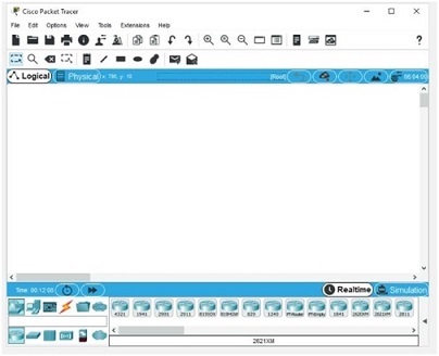
Figure 1: The main Packet Tracer window Source: Cisco Systems, Inc.
3. Hover your mouse over each device in the bottom row and click Switches. In the middle pane, you see a selection of switches. Click and drag the second switch from the left, which is labelled PT-Switch. Drag and drop the switch into the main Packet Tracer window.
4. Next, on the top row of device types, click End Devices. In the middle pane, click and drag PC into the main screen. Repeat this action until there are two PCs and one switch (see Figure 2).
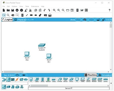
Figure 2 Two PCs and one switch in Packet Tracer Source: Cisco Systems, Inc.
5. Next, you'll connect the PCs to the switch. Click the Connections icon on the top row of device types. In the middle pane, click the Copper Straight-Through cable, which looks like a solid black line.
6. Click PC0 and then click FastEthernet0 to plug the cable into PC0's Ethernet port. Click Switch0 and click FastEthernet0/1 to plug the other end of the cable into the switch. Repeat the process for PC1, but choose FastEthernet1/1 on the switch this time. Your Packet Tracer diagram should look like Figure 3. Congratulations, you have built your first LAN with Packet Tracer!
7. Before this LAN can be useful, you must assign an IP address to each PC. Hover your mouse over each PC and you'll see that the IP address column of the pop-up window reads "<not set>." Click PC0 to open the PC0 configuration dialog box. Click the Desktop tab (see Figure 4).
8. Click IP Configuration and fill in or confirm the following values:
• IP Address: 172.20.1.1
• Subnet Mask: 255.255.0.0 (this value is filled in automatically)
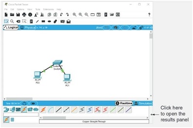
Figure 3 Two PCs connected to a switch in Packet Tracer Source: Cisco Systems, Inc.
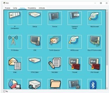
Figure 4 The Desktop tab for configuring a PC Source: Cisco Systems, Inc.
9. Close the PC0 configuration dialog box and then repeat the process for PC1, using IP address 172.20.1.2 with the same subnet mask. Close the PC1 configuration dialog box. 10.Hover your mouse over each PC. You'll see that the IP address column of the pop-up window shows the new IP address.
11. To send a packet from PC0 to PC1, click the closed envelope icon in the top menus (the second icon from the right). Click PC0 and then click PC1. It doesn't look like much happened. To see results, you need to open the results pane in the lower-right corner of the window. Click the left arrow shown in Figure 3 to see a panel open. You should see a Successful result (see Figure 5).
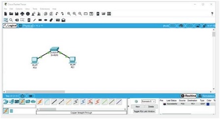
Figure 5 The results panel Source: Cisco Systems, Inc.
12. With the results panel open, you can now send more packets and see the results in the panel.
13. Close Packet Tracer. When prompted to save the file, click Yes.
14. Attach the saved Packet Tracer file with your submission.
15. Briefly describe what you've learned from this task.
PART 2 activities give you critical thinking challenges. They give you an opportunity to use the skills you have learned to perform a task without step-by-step instructions. Case projects offer a practical networking setup for which you supply a written solution. Then you will have to evaluate the solution provided through the reflective report writing.
Challenge One: Determining That Your Computer Is Connected to a Switch
Objective: Use packet information captured with Wireshark to determine whether your computer is attached to a network with a switch.
Description: You've learned the difference between hubs and switches during your study. In this challenge, set up a test that determines that your computer is connected to a switch and not to hub. Write a short memo to your instructor to address the following questions:
1. What filter options (if any) did you configure in Wireshark?
2. What commands did you use to generate packets on the network?
3. What IP addresses did you attempt to communicate with?
4. What was your result? Is your computer attached to a hub or switch?
5. Why did you come to this conclusion?
Challenge Two
ABC.com has 150 networked computers and six servers and uses a star topology wired network to reach employees' offices, with a bus interconnecting four floors in its office building. Because of a staggering influx of Internet business, the network administrator's
task is to boost network performance and availability as much as possible. The company also wants a network design that's easy to reconfigure and change because workgroups form and disband frequently, and their membership changes regularly. All computers must share sensitive data and control access to customer files and databases. Aside from the customer
information and billing databases, which run on all servers, employees' desktop computers
must run standard word-processing and spreadsheet programs.
Fill in the following lines to evaluate the requirements for this network. After you finish, determine the best network topology or topology combination for the company. On a blank piece of paper, sketch the network design you think best suits the needs of ABC.com.
Remember: High performance and easy reconfiguration are your primary design goals!
1. What type of topology should be used in this network?
2. Will the network be peer-to-peer or server based?
3. How many computers will be attached to the network?
4. What kind of networking device is easiest to reconfigure?
5. What kind offers the best access to the network medium's bandwidth between pairs of devices
Challenge Three
You work at a help desk and have just received a call from an employee who says she can't access network resources. You want the employee to view her IP address configuration. Write an e-mail to the employee, explaining what command-line program to use and how she can use it to find the information you need. After following your instructions, the employee tells you that her IP address is 169.254.14.11 with the subnet mask 255.255.0.0.
What conclusion can you make from this information?
Challenge Four
You have configured a LAN with 25 workstations, three network printers, and two servers. The workstations and printers will have dynamically assigned IP addresses, and the printers always need to have the same IP address assigned. The servers will have static IP addresses.
What should you install on one of the servers, and what are some of the configuration options?
Attachment:- Data Communication and Networks.rar