Reference no: EM132115836
Questions -
Q1. A half-wave rectifier such as shown in figure 2.2(a) has a 2 kΩ load. The input is a 120 V (rms), 60 Hz signal and the transformer is a 10:1 step-down transformer. The diode has a cut-in voltage of Vγ = 0.7 V (rf = 0).
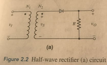
(a) What is the peak output voltage?
(b) Determine the peak diode current.
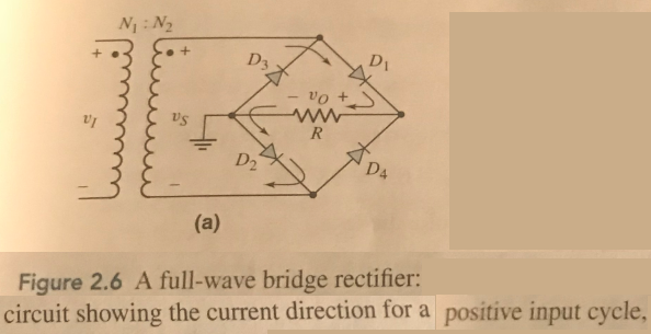
Q2. The input signal voltage to the full-wave rectifier circuit in figure 2.6(a) in the text v1 = 160sin[2π(60)t]V. Assume Vγ = 0.7 V for each diode. Determine the required turn's ratio of the transformer to produce a peak output voltage of (a) 25 V, and (b) 100 V. (c) What must be the diode PIV rating for each case?
Q3. The full-wave rectifier circuit shown in figure P2.12 has an input signal whose frequency is 60 Hz. The rms value of vs = 8.5 V. Assume each diode cut-in volatage is Vγ = 0.7 V.
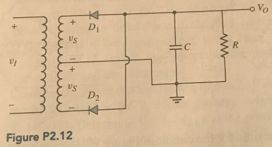
(a) What is the maximum value of Vo?
(b) if R = 10Ω, determine the value of C such that the ripple voltage is no larger than 0.25 V.
(c) What must be the PIV rating of each diode?
Q4. Consider the full-wave bridge rectifier circuit. The input signal is 120V (rms) at 60 Hz. The load resistance is RL = 250 Ω. The peak output voltage is to be 9V and the ripple voltage is to be no more than 5 percent. Determine the require turns ratio and the required value of filter capacitance.