What is the minimum resistance you measure

Assignment Help Electrical Engineering
Reference no: EM131667473

Assignemnt: DC POWER SUPPLY:

Find the DC power supply associated with your workbench. Using the proper cables, connect the DC power supply to a voltage meter. Be sure you change the meter from measuring resistance to actually measure voltage. Using the controls on the DC Power supply, adjust the output voltage to 5V and to 10V. Notice that you may need to use different outputs to get the desired 0V-10V range. Show the instructor that you can set the voltage to 10V and 5V.

OHMS LAW:

Select two resistors from the resistor selection bins. The first resistor must be 1W or 10W. This resistor will be used as a "current sense" resistor, called Rs. Then select another resistor, R1, that is within the range 1kW - R1 - 50kW.

1. Measure, with a Multimeter, the resistance values of R1 and Rs.

2. Connect R1 and Rs in series on the breadboard.

3. Now measure the total series resistance. Does the Rs resistance "really" impact the total resistance?

4. Make sure the power is off to the DC power supply. Then connect the positive DC voltage terminal to R1. Then connect the ground (GND) DC voltage terminal to the Rs using a combination of cables and wires.

5. Calculate, using Ohms law, how much current you expect to flow through R1, if the DC voltage is 5V. Record this value and the equation you used.

6. Ensure the DC voltage is still 5V. Then measure the voltage across Rs. Using your recorded resistance value and measured voltage, calculate the current through R1. Does it match your calculations in step 5?

7. Show your results to the instructor and get signoff.

8. Turn off the DC power supply.

Potentiometer Part A:

Obtain a 10K potentiometer and complete the following tasks, first with no DC Power connected.

1. Measure and record the total resistance across the device. (i.e. the outer terminals).

2. Turn the "knob" on the potentiometer. Does the total resistance change?

3. Measure the resistance between an outer terminal of the potentiometer and the middle terminal, as you adjust the "knob".

a. What is the minimum resistance you measure

b. What is the maximum resistance?

4. Adjust the resistance between an outer terminal and the middle terminal so it is 5KW.

Show your results to the instructor and get signoff.

Potentiometer Part B:

Now, apply 5V DC across the potentiometer and measure the voltage from the middle terminal to the ground side of the potentiometer, we will call this the output voltage. Answer the following questions:

1. What is the output voltage if the potentiometer was left at the 5KW position defined in the previous section?

2. What do you expect the minimum output voltage to be? What do you expect the maximum to be?

3. Turn the knob and validate your results from the previous step.

4. Disconnect the DC power supply and then measure the output resistance at the point where your output voltage reaches its minimum. What is the value of this resistance? Does this value make sense to you?

3B report Example :

Why this is a solid 3B Report

1) It is not a short lab report

2) It is concise, covers the key learning objectives, is technically detailed, and has the right balance between the three required components (Objectives, Accomplishments, Next Steps)

Improvements Needed

1) Grammar / Editing

2) Sentence Flow

We explored the transistor 2N3904's three active regions. We analyzed how the measured parameters of junction's currents and voltages on how it affected its characteristics. We computed the beta value from the measured values.

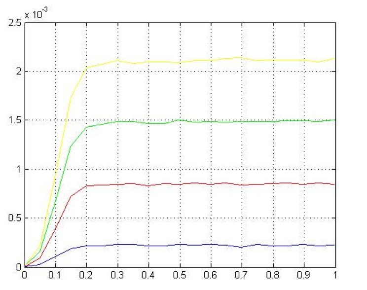
We build a circuit capable of applying variable voltage across the BJT's baseemitter terminals. Our measured and theoretical I-V values confirmed that all three regions of operation were correct. Our I-V plot characteristic matched the BJT's datasheet within 5%. In figure1, with increasing fixed IB the IC slightly changed with VCE, causing the I-V curve to had non-zero slope in the active region. If the I-V curves slope were extended to the left, our early voltage would be around 200. This was a good transistor because of its wide dc-bias range region. Our circuit exhibited different beta levels from 180 to 220, thus our circuit bias point was sensitive and dependent to the transistor's beta. The beta governed our circuit amplification property. Ideally, we would want to our circuit to be independent of beta to create varieties of transistors. With basic BJT understandings, we will be adding another BJT stage to our audio amplifier design to achieve the best output gain next week. (picture of the goal)
2157_BJT-Stage.jpg

Reference no: EM131667473

Questions Cloud

Perspective of an emergency planner for the real-world : You will again approach it from the perspective of an emergency planner for the real-world county that you have employed all term.
Compare and contrast open and closed systems : compare and contrast open and closed systems. Explain why almost all businesses today have an open system.
Describe the qualitative design of the article : Present the strengths and limitations of this type of design according to the textbook, and explain how these strengths and limitations are reflected in study.
Explain the three roles that managers play : Define and explain the three roles that managers play, according to Henry Mintzberg.
What is the minimum resistance you measure : What is the minimum resistance you measure? Calculate the current through R1. Does it match your calculations in step 5?
Write one research summary that uses a quantitative research : Quantitative research- A Quantitative Study on the Condom-Use Behaviors of Eighteen- to Twenty-Four-Year-Old Urban African American Males
Key principles that underlie strategic positioning : Explain the three key principles that underlie strategic positioning.
Three key principles that underlie strategic positioning : Explain the three key principles that underlie strategic positioning.
Primary data to answer specific research : Create a cover letter and a questionnaire, which will be used to distribute to collect primary data to answer specific research question(s).

Reviews

Write a Review

Electrical Engineering Questions & Answers

  Determine the digital frequencies of the sampled signal

A composite analog signal is given in the following expression: x(t)=1.2 sin(2pi60ft)+0.0001cos(2pi1ft) -If this signal was sampled at 1000 Hz, derive the expression for the sampled sequence x[n] with n being the sampling index.

  Find value of multiplier resistor to obtain full defection

An AC Voltmeter uses a bridge rectifier and 100 ohm PMMC which requires a 1mA DC current for full-scale deflection. Assuming ideal diodes, calculate the value of the multiplier resistor to obtain full scale deflection with 10 V AC applied to the i..

  Calculate plant load factor and plant use factor of station

A power station has two 60 MW units each running for 7000hours a year and one 30MW unit running for 1500 hours a year. The energy produce is 700 x106 Kwh per year,Calculate; 1 plant load factor 2 plant use factor

  What is the total flux in the core

A transformer core with an effective mean path length of 10 in has a 300-turn coil wrapped around one leg. Its cross-sectional area is 0.25 in2, and its magnetization curve is shown in Figure 1-10c. If current of 0.25 A is flowing in the coil, wha..

  Obtain a transfer function using the laplace transform

Understand forward and inverse Laplace transform and obtain the initial value and final values using Laplace transform and Derive the integrodifferential equation that governs the behavior of the current

  What is the numerical aperture of this fiber

What is the numerical aperture of this fiber? What is the limiting bit rate for transmission over 10 km at 0.88 µm? Use 1.45 for the refractive index of the cladding.

  The main methods of starting 3 phase induction motors

Give the main methods of starting 3 phase induction motors. - Which method is considered best for starting squirrel cage induction motors.

  Design a noninverting amplifier

Design a noninverting amplifier with an appropriate closed-loop voltage gain of 150 and a minimum input impedance of 100Ω using a 741 op-amp. Include bias current compensation.

  Find how many bits from station c have already been sent

Notice that when C begins sending, the signal due to the frame from A has not reached station C yet. If it reached, station C would not send it. How many bits from station C have already been sent when it hears the signal from A

  What is the value of q for the initial acceleration

Two particles are fixed on an x axis. Particle 1 of charge 60.5 µC is located at x = -18.7 cm; particle 2 of charge Q is located at x = 9.53 cm. Particle 3 of charge magnitude 51.7 µC is released from rest on the y axis at y = 27.4 cm.

  What is the maximum doppler for a vehicle speed

A)what is the maximum Doppler for a vehicle speed of 160 km/hr at 900MHz. B)what is the minimum doppler(most negative for this case) C)for this range of Doppler what is the corresponding speed at 1800MHZ

  Generate the mips code for aforementioned program segment

Assume that all variables reside in the memory and they are addressable as offsets from $t0. The value of A resides at the offset of 0. Generate the MIPS code for the aforementioned program segment.

Free Assignment Quote

Assured A++ Grade

Get guaranteed satisfaction & time on delivery in every assignment order you paid with us! We ensure premium quality solution document along with free turntin report!

All rights reserved! Copyrights ©2019-2020 ExpertsMind IT Educational Pvt Ltd