Reference no: EM13528118
Problem 1:
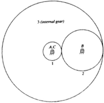
The gear set shown in Figure below consists of three 20 degree full-depth spur gears with a module of 8mm and the following tooth numbers: N1=20, N2=40, and N3=100. Gear 2 is an idler. The unit transmits 20kW at a rotational speed of 1000 rev/min of gear 1 in the clockwise direction. Determine the following:
(a) The center distances
(b) The rotational velocity (magnitude and direction) of each gear
(c) The torque transmitted to each shaft
(d) All forces (magnitude and direction) on each gear

Problem 2:
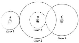
A double-reduction gear set has the configuration shown in Figure below, where gear 1 is rigidly attached to shaft, gear 2 and 3 rigidly fastened to shaft B, and gear 4 is fastened to shaft C. Gear 1 and 2 have 32 teeth and 80 teeth, respectively and are 20 degree full-depth spur gears with a module of 4mm. Gear 3 and 4 have 24 teeth and 50 teeth, respectively, and are 25 degree full depth spur gears with a module of 6mm. The system transmits 30kw at a rotational speed of 1200 rev/min of gear 1 in the clockwise direction. Find the speed and the torque transmitted by each shaft. Determine the shaft acting on each shaft

Problem 3:
A single-treaded worm has an axial pitch of 20mm and a pitch diameter of 50 mm. The worm rotates at 500 rev/min and drives a gear having 40 teeth and a 25 degree transverse pressure angle. The power transmitted is 0.5 kW. Determine (a) the lead angle of the worm, (b) the center distance between worm and gear, and (c) the tangential, radial, and trust forces on the worm gear
Problem 4:
A pair of crossed helical gears connects shafts making an angle of 45 degree. The right hand pinion has 36 teeth and a helix angle of 20 degree. The right hand gear has 48 teeth and its module in the normal plane is 2.5mm. Determine (a) the helix angle of the gear (b). Circular pitch in the normal plane (c) module of the pinion in its plane of rotation (d) module of the gear in its plane of rotation (e) center distance
Problem 5:
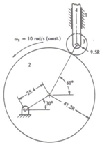
(a) Draw an equivalent linkage of the slider-crank type for the cam mechanism shown below (b) Analyze the equivalent linkage: compute the velocity and acceleration of the follower.

Section 2:
Write a review paper of one mechanism we have learned this semester including its application, changes in design with time, and future direction. (For example, you can talk about the history and application of Cam, how people change the design of Cam to meet different application needs, and what is the future improvement and suggestion of Cam design etc).