Reference no: EM132608584
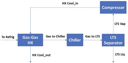
You are asked to model a simplified refrigerated gas plant (see block diagram below) to determine the operating conditions required to meet the product recovery target. For this process scenario, a 50% recovery of C4 components (i.e., i-Butane and n-Butane) is required to be achieved in the bottom (liquid) outlet stream leaving the separator.

The hydrocarbon stream (labelled To Refrig above) specifications are given in the table below:
|
Temperature
|
40°C
|
|
Pressure
|
2000 kPa
|
|
Flow Rate
|
2000 kmol/h
|
|
Composition (mol/mol)
|
|
|
Methane
|
0.5266
|
|
Propane
|
0.0790
|
|
i-Butane
|
0.0216
|
|
n-Butane
|
0.0142
|
|
i-Pentane
|
0.0074
|
|
n-Pentane
|
0.0074
|
|
n-Hexane
|
0.0142
|
|
Carbon Dioxide
|
0.0358
|
|
Nitrogen
|
0.0716
|
|
Ethane
|
0.2222
|
The To Refrig stream is cooled down in two stages. Firstly, To Refrig is fed into a shell and tube heat exchanger (Gas-Gas HX), which uses a downstream cold stream (HX Cool_in). Use the Single End Point model available in HYSYS to simulate the operation of the Gas-Gas HX unit subject to the specifications provided below:
Gas-Gas HX specifications
Stream:
Tube Side Inlet To Refrig
Tube Side Outlet Gas to Chiller
Shell Side Inlet HX Cool_in
Shell Side Outlet HX Cool_out
Pressure drop
Shell side 10 kPa
Tube side 20 kPa
Shell type
The minimum temperature difference between streams To Refrig and HX Cool_out must be maintained at 10 °C.
After the first cooling stage, the Gas to Chiller stream is further cooled down using a cooler (Chiller). The pressure drop experienced across the Chiller is 30kPa. The output-cooled stream (Gas to LTS) is at -5 °C, and is finally flashed in an LTS separator to separate the remaining liquid.
After separation, the top vapour stream LTS Vap is passed through a compressor (Compressor) to increase the pressure of the stream to 2000 kPa. The outlet stream from the compressor HX Cool_in is used as the cooling stream to the heat exchanger (Gas-Gas HX) process unit.
Answer the following questions:
Question 1. Build a process flowsheet to represent the simplified refrigerated gas plant described above by adding the appropriate unit operation models from the HYSYS model palette, making sure that you connect the units in the direction of the main stream flow to avoid any calculation errors.
Question 2. What is the calculated value of the global heat transfer coefficient as given by UA for the Gas-Gas HX model in kJ °C-1 h-1?
Question 3. What is the cooling duty determined for the Chiller model in kW?
Question 4. What is the temperature (°C) of the Gas to Chiller stream?
Question 5. What is the power requirement determined for the compressor (Compressor) in kW?
Question 6. Use a HYSYS spreadsheet unit to calculate the % recovery of the C4 components (i.e., i-Butane and n-Butane) in the bottom stream (LTS Liq) of the flash separator. What is the % C4 recovery in this case? The % C4 recovery can be computed as:
C4 recovery (%) = 100 x (Molar flowrate iButane + Molar flowrate nButane in LTS Liq)/(Molar flowrate iButane + Molar flowrate nButane in To Refrig)
Question 7. Add an Adjust unit to manipulate the temperature of the Gas to LTS stream to achieve the 50% recovery specification for the C4 products. What chiller outlet temperature is then required to achieve the required product recovery specification?
Question 8. Briefly explain why manipulating the temperature of the To Refrig stream instead of the Gas to LTS stream would not achieve the required product recovery specification.