Reference no: EM133098705
Question 1. Here we look at a water immersion lens. The glass lens with n = 1.5 has a convex front surface with r = 10 mm and a flat back surface, and is 8 mm thick. First, consider the lens in air on both sides.
a. Write the matrix for the lens.
b. Find the front and back principal planes.
c. Find the front and back focal lengths.
d. Draw the lens with the principal planes and focal points labeled.
e,f,g,h. Repeat a,b,c,d with the left side of the lens immersed in water.
Question 2. Design a convex mirror to be used on the passenger's side of a car. Choose a radius of curvature and diameter that will provide a useful field of view.
Show your design in object space (i.e. with the driver's eye imaged in themirror to illustrate how it operates.Your answer may disagree with mine, depending on your choice of field of view and dimensions of the car.
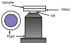
Question 3. In TIRF microscopy, light is directed through a high-index-of-refractionmaterial, such as glass, to the sample. The light is transmitted throughan annulus in the pupil plane so that it is incident on the glass-to-sample interface at only angles greater than the critical angle, thus undergoing total internal reflection. See the figure. An evanescent wave at very small distances into the sample (much less than a wavelength), is absorbed by fluores centmaterial in the sample, and the fluorescent light is imaged. We consider a microscope with an infinity-corrected 100X, 1.45NA oil-immersion objective. Thismicroscope vendor uses a 200 mm focal lengthtube lens. Assume the glass slide, the oil, and the first glass element of theobjective all have n = 1.5 and the sample consists mostly of water withn = 1.33.
a. What are the front and back focal lengths of the objective? You willneed to do a little work to determine this as we have not previously considered magnification by a microscope with the first medium different from air.
b. What is the angle of incidence, on the glass-to-sample interface, of aray that just passes through the numerical aperture of the objective? Whatis the critical angle?
c. What is the radius of the pupil? What is the inner radius of the annulus to ensure that the incident light undergoes total reflection?
d. Assume the emitted light from the fluorescent material is collected through the hatched region of the pupil shown in the figure through a beampslitter, what is the numerical aperture for collecting this light?

Question 4. Here we consider system with two scanning mirrors to scan a laser beam in the focal plane of a microscope objective. We relay the scanners to the microscope pupil via a telescope consisting of a small first lens of focal length f1 = 75 mm and a larger lens of focal length f2 = 200 mm separated by the sum of their focal lengths. Ideally the second lens functions like a tube lens in that its back focal point is at the pupil of the objective and a real image is formed at the point where the rays cross in the figure.
Ideally, we would place the scanning mirrors at the front focal plane of the first lens so they would be conjugate to the microscope pupil. However, the two mirrors cannot occupy the same location so we place them 10 mm before and after this location. We will move the mirrors so that the laser beam moves through ±5 deg at the mirrors.
a. Where are the scanner images (as seen through the two relay lenses) relative to the pupil?
b. What is the angle of the scan after the two lenses (i.e. at these images).
c. As the beam is scanned, it moves away from the center of the pupil.How far does it move? Draw pictures to show this.
d. If the focal length of the objective is 10 mm what is the full field of view of the scanned image in millimeters?
