Reference no: EM131059930
Half-Wave and Full-Wave Rectifier
Introduction:
The lab is based on half-wave and full-wave rectifiers. Rectifiers are widely used in power supplies to provide the required DC voltage.
Please review the following videos before getting started with this lab:
1. Watch the video: "Video 3: Basic Electrical Components"-
https://content.grantham.edu/at/EE212/1-20-2015/week2/Fundamental_of_Breadboard.mp4
2. Watch the video: "Video 4: Fundamentals of breadboard"
https://content.grantham.edu/at/EE212/1-20-2015/week2/Basic_Electrical_Components.mp4
3. Watch the video: "Video 5: Simple resistive circuit with NI myDAQ"
https://content.grantham.edu/at/EE212/1-20-2015/week2/Simple_Resistive_Circuit_with_NI_myDAQ.mp4
Materials and Equipment:
Materials:
• Simulated Parts (Multisim):
o 30/3 Vrms center-tapped transformer
o Two diodes 1N4001
o Two 2.2 kΩ resistors
o One 100 μF, 50 V electrolytic capacitor
o One fuse (any rating is fine since it is for simulation only)
• Hardware Parts (In the Toolbox):
o Two diodes 1N4001
o Two 2.2 kΩ resistors
o One 100 μF, 50 V electrolytic capacitor
Equipment:
• Virtual Instruments (Multisim):
o Agilent Function Generator
o Tektronix oscilloscope
• Hardware Equipment:
o Breadboard
o NI myDAQ Instrument Device
o Screw Driver
o Screw Terminal connector
o Jumper wires
o Oscilloscope and Function generator from NI ELVISmx Intrument Launcher
Procedure:
This lab has to be implemented in both software (running simulations on Multisim) and hardware (using NI myDAQ)
Part A: Half wave rectification:

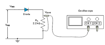
Figure 1
Software (Multisim):
1. Construct the circuit of a half-wave rectifier in Figure 1 in Multisim. Use a function generator to provide the AC input of Vacand use a center tapped transformer to obtain VSEC. Be sure to set the tolerance of the resistor to 20%.
2. Connect the Tektronix oscilloscope so that channel 1 is across the transformer and channel 2 is across the load resistor (RL). Observe the waveforms VSEC and VLOAD.
3. The output isn't very useful as a dc source because of the variations in the output waveform. Connect a 100 μF capacitor (C1) with a tolerance of 20% in parallel with the load resistor (RL). (Note the polarity of the capacitor).
4. Measure the dc load voltage, VLOAD, and the peak-to-peak ripple voltage, VRIPPLE, of the output. Measure the ripple frequency. Tabulate all data gathered and compare the results with and without the filter capacitor.
Hardware (NI myDAQ):
1. Using the voltage VSEC obtained from the simulation, build the circuit in Figure 1 on the breadboard with VSEC as an input, which connects to the diode and load resistor RL in series. (See Figure 3)
2. Using the jumper wires, screw driver and screw terminal connector, connect the board to NI MyDAQ Instrument Device to analyze the circuit.
3. Use channel AO0 on the NI myDAQ Instrument Device to provide the input (VSEC) and channel AI0 to measure the output voltage(VLOAD).
4. Using the function generator from NI ELVISmx Instrument Launcher, provide the input voltage VSEC to the circuit. Measure the output voltage VLOAD, across the load RL using the oscilloscope.
5. Repeat steps 3 and 4 with a 100uF capacitor if you notice any variations in the output.

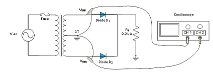
Figure 2
Review questions:
1. What is the purpose of having a half-wave rectifier in the circuit?
2. Describe the procedure in this lab to arrive at the final design of both the hardware portion and the software portion to achieve the design objectives?
3. Discuss the impact of having the capacitor on the output voltage and the effect of additional load on the ripple voltage.
Deliverables:
1. Measured voltage VSEC, the output peak voltage, VLOAD and ripple voltage VRIPPLE. Capture screenshots of your measurements from Multisim.
2. Place your student ID card on the breadboard and take a picture of the circuit board and pin out on the NI myDAQ device.
3. Take screenshots of the measurements obtained from function generator and oscilloscope on the NI ELVISmx Instrument Launcher on your screen.
Part B: Full wave rectification:
Software (Multisim):
1. Construct the circuit of a half-wave rectifier in Figure 3 in Multisim. Use a function generator to provide the AC input of Vacand use a center tapped transformer to obtain VSEC. Notice that the ground for the circuit has changed. Check your circuit carefully before applying power.
2. Connect the Tektronix oscilloscope so that each channel is across each diode. Observe the waveforms VSEC across each diode and then observe the VLOAD.
3. Connect a 100 μF capacitor (C1) with a tolerance of 20% in parallel with the load resistor (RL). (Note the polarity of the capacitor).
4. Measure the dc load voltage, VLOAD, and the peak-to-peak ripple voltage, VRIPPLE, of the output. Measure the ripple frequency. Tabulate all data gathered and compare the results with and without the filter capacitor.

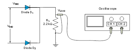
Figure 3
Hardware (NI myDAQ):
1. Using twice the voltage VSEC obtained from the simulation, build the circuit in Figure 3 on the breadboard with 2*VSEC as an input, which connects to the two diodes and load resistor RL in series. (See Figure 4)
2. Using the jumper wires, screw driver and screw terminal connector, connect the board to NI MyDAQ Instrument Device to analyze the circuit.
3. Use channel AO0 on the NI myDAQ Instrument Device to provide the input (2*VSEC) and channel AI0 to measure the output voltage (VLOAD).
4. Using the function generator from NI ELVISmx Instrument Launcher, provide the input voltage VSEC to the circuit. Measure the output voltage VLOAD, across the load RL using the oscilloscope.
5. Repeat steps 3 and 4 with a 100uF capacitor if you notice any variations in the output.

Figure 4
Review questions:
1. What is the purpose of having a full-wave rectifier in the circuit?
2. Describe the procedure in this lab to arrive at the final design of both the hardware portion and the software portion to achieve the design objectives?
3. Discuss the impact of having the capacitor on the output voltage and the effect of additional load on the ripple voltage.
4. How is the output of the full-wave rectifier different from half-wave rectifier?
Deliverables:
1. Measured voltage VSEC, the output peak voltage, VLOAD and ripple voltage VRIPPLE. Capture screenshots of your measurements from Multisim.
2. Place your student ID card on the breadboard and take a picture of the circuit board and pin out on the NI myDAQ device.
3. Capture screenshots of your measurements from the NI ELVISmx Instrument Launcher showing both the input from the function generator and output on the oscilloscope on your screen.
Lab Report:
• Use the Lab report template found in the "Tools and Template" link in the navigation center.
• Include all the deliverables from Part A and Part B.
• Include all the screenshots of the measurements from Multisim, circuit design on the breadboard using NI myDAQ device and measurements from MI ELVISmx Instrument Launcher.
• Save the document as Lab2YourGID.docx (ex: Lab2G00050331.docx) and submit in Blackboard.