Reference no: EM131025848
1. Objective
The objectives of the experiment are to measure the surface pressure distribution on an airfoil set at various angles of attack, to calculate the pressure coefficient, the lift coefficient, and the lift force acting on the airfoil. In addition, the uncertainty of the results has to be calculated, and the results have to be compared with benchmark data.
2. Experiment Process
Setup
The experiment measurement system includes: the wind tunnel, the airfoil, and the multiport manometer (see Figure 1). The manometers on the manometer panel indicate the pressures at the surface pressure taps. The temperature in the test section is measure with a thermometer. The angle of attack is set using a handle, located below the test section, which rotates the table the airfoil is installed on. Before taking the measurements, setup the targeted flow conditions in the tunnel test section. A Reynolds number of 143000 (corresponding to 7.04 m/s free stream velocity) is recommended for the experiment to match the testing conditions for the available benchmark data.
Data Acquisition
Each student group acquires pressures measurements (see Figure 1 for a sample pressure profile) at the surface pressure taps located on the airfoil perimeter for the airfoil set at various angles of attack as specified by the TA. Use the spreadsheet provided in the appendix of this handout to record the data. Make sure to measure the free-stream velocity at the desired angle of attack.
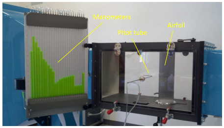
Figure 1- The test section with the airfoil and Pitot tube installed during a test; the manometers indicate the pressure distribution around the airfoil.
3.3 Data Reduction
Data reduction includes calculation of the following quantities:
1. free-stream velocity U∞ and the corresponding flow Reynolds number, Re = U∞ · c/n, where c is the chord length of the airfoil, and n is the kinematic viscosity of air (use the temperature measured by the thermometer inside the test section to determine n from fluid property tables).
2. Pressure coefficients (using Equation 1 and the readings on ports 0 to 18) on the airfoil surface. Plot Cp versus x/c (x is the coordinate along the chord line) for all the angles of attack employed in the experiment. Include the uncertainty estimate for the pressure coefficient. Compare your measurements with the benchmark data.
3. Lift force on the airfoil obtained by integrating the measured pressure over the airfoil surface. Use of the trapezoidal rule, provided in Appendix A, for the numerical integration.
4. Lift coefficient, CL, given by equation (3). Calculate the lift coefficient per unit span length and plot the points obtained experimentally with the CL /unit span length versus the angle of attack, α, provided. Include the uncertainty estimate for the lift coefficient. Compare your measurements with the benchmark data.
3.4. Uncertainty Assessment
Uncertainties for the experimentally measured lift coefficients will be evaluated. The block diagram for error propagations in the measurements is provided in Figure 2. Based on previous experiments, it was found that bias and precision uncertainty for the ρ, U∞ , θ, s, and c are negligible, hence for the present analysis only include the bias uncertainty for pi - p∞. To facilitate the uncertainty analysis you will have to estimate the bias and precision uncertainties for the individual measured variables. Note that the uncertainty assessment does not include error sources such as undetected leaks in the pressure tubing, model orifice effects, vibration effects on the probes and unsteady flow effects.
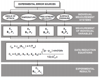
Figure 2- The block diagram for the measurement system and data reduction equations for determination of the lift coefficient.
Uncertainty in the pressure coefficient
The total uncertainty for the pressure coefficient measured at each pressure tap is given by the equation
U2Cp = B2Cp + P2Cp (5)
The bias uncertainty in Equation (5) is the same as that for the pressure taps. Neglecting the correlated bias uncertainties and discarding the terms with negligible bias uncertainties
B2Cp = i=1Σj θi2Bi2 = θ2(p_i - p_∞) B2(p_i - p_∞) (6)
where Bi is the bias uncertainty for the individual variable and θi = ∂Cp / ∂Xi are sensitivity coefficients.
The sensitivity coefficient θ(p_i - p_∞) , evaluated using the average values for the individual variables, is given by
θ2(p_i - p_∞)= ∂Cp / ∂(pi - p∞) = 2 / ρU∞2
The precision uncertainty for each pressure tap in Equation (5) is estimated as
PCp = 2SCp / √M (7)
where SCp is the standard deviation of the pressure coefficients at each pressure tap evaluated for M = 10 repeated tests. Precision uncertainty will have different values for each of the 18 taps. Based on previous measurements, an average value for the precision uncertainty will be provided.
Uncertainty in coefficient of lift
The data reduction equation for the lift coefficient is Equation 3 and it is of the form
Cp = f (pi - p∞, θ, s, r, U∞, c) . You should only consider bias uncertainty for (pi - p∞). The total uncertainty for the measurement of the lift coefficient is given by
U2CL = B2CL + P2CL (8)
The bias uncertainty in equation (8), neglecting the correlated bias uncertainty and the terms assumed with negligible bias uncertainty, is given by
B2CL = i=1Σj θi2Bi2 = θ2(p_i - p_∞) B2(p_i - p_∞) (9)
Given the above assumptions and using the lift force determined by integration (Equation 4), the expression for the bias uncertainty of the lift coefficient is
B2CL = B2(p_i - p_∞) i=1Σk [∂CL / ∂(pi - p∞)]2 = [B(p_i - p_∞) / 0.5 ρ U2∞ c]2 i=1Σk[sin (θi) dsi]2
Notations used in Equation (10) are defined in Appendix B (k = 29). The precision uncertainty in Equation (10) was estimated as
PCL = 2SCL √M (11)
where SCL is the standard deviation of the lift coefficients evaluated for M = 10 repeated tests. Based on previous measurements, an average value for the precision uncertainty will be provided to facilitate the uncertainty analysis.
4. Data Analysis
Measurements obtained in the experiments will be compared with benchmark data. Benchmark data for pressure distribution coefficients and lift coefficients on a Clark-Y airfoil set at various angles of attack and Re are those of Marchman and Werme (1984). The benchmark data is plotted in Figure 3.
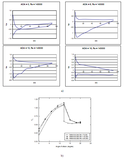
Figure 3 - Reference data (Marchman and Werme, 1984); a) Distribution of the pressure coefficients for α = 0°, 4°, 6°, 8°, 12°, 14° and Re = 143,000; b) Variation of the lift coefficient with the angle of attack.
Discussion
Answer the following questions:
1. If the lift L is a function of the free-stream velocity U∞, density ρ, chord c, angle of attack α, and viscosity ν, what are the dimensionless groups (π parameters) that characterize this problem?
2. How do the experimental measurements of the pressure distribution apply to a full-scale aircraft having a similar airfoil section?