Reference no: EM132878813
UTS 49316 Materials Handling - University of Technology Sydney
Part - Pneumatic Conveyors Design
Pneumatic Conveyor
The dilute-phase vacuum conveying system shown in Figure 1 is transferring 9.75 + P/3) t.h-1 of grain, according to the following specification:
• Horizontal conveying pipeline: galvanized steel; internal diameter, D = 100 + Q mm; total length, L = 112 + (PQ/4) m; internal roughness, ε = 0.10 mm.
• Dehumidifier pressure loss = 10 + P kPa.
• Receiving bin filter pressure loss = 5 + (Q/3) kPa.
• Temperature of air along conveying pipeline and through filter, t = 20 + P °C.
• Absolute viscosity of air at 20 + P °C, μf = [1.4 + (QP/100)] x 10-5 Pa.s.
• Atmospheric air pressure, Patm = 101 kPa-abs.
• Atmospheric air temperature, tatm = 20 °C.
• Acceleration due to gravity, g = 9.81 m.s-2.
• Pitot tube measurements (in between filter and blower and close to filter): average air velocity = 40 + (PQ/100) m.s-1; static gauge air pressure = - (70 + Q) kPa-g.
You are required to determine the following items:
(a) Total conveying pipeline pressure drop, Δpt (kPa).
(b) Density of air at the pitot tube, ρfp (kg.m-3).
(c) Conveying air mass flow rate, mf (kg.s-1).
(d) Superficial conveying air velocity at the inlet and the exit of the conveying pipeline, Vfi and Vfe (m.s-1), respectively.
(e) Mean superficial air velocity for the pipeline (Vfm), the Reynolds No. (Re), the air-only pipe wall friction factor (λf) and the air-only pressure drop (Δpf)
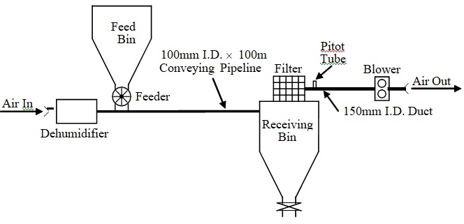
Figure 1: Vacuum Dilute-Phase Pneumatic Conveying System