Reference no: EM132801769
Unit 15 Electrical Circuits and their Applications - Pearson BTEC Level 3 National Extended Certificate in Applied Science
Learning aim 1: Understand electrical symbols, units, definitions, relationships and properties of circuit components for use in the construction of circuits.
Learning aim 2: Construct series and parallel circuits for use in standard electrical applications and measure electrical values.
Assignment - Electric Circuits
You are a trainee technician working for a company that specialises in producing specialist medical equipment such as electrocardiography, electromyography and electroencephalography machines. As part of your induction, you have been asked to produce a report that demonstrates your knowledge of electrical concepts and shows that you are able to assemble various electrical circuits.
Using your notes and research, produce an ‘Electrical Circuits Information Report' containing the following sections:
Section 1 - Electrical symbols, units and definitions
State the symbols for the following cell components in a table:
cell
battery
switch
filament lamp
fixed resistor
thermistor
light emitting diode (LED)
light-dependent resistor (LDR)
rheostat
capacitor
voltmeter
ammeter.
Produce a ‘Glossary of Terms' that defines and gives a brief explanation of each of the following: -
current (ampere)
potential difference (volt)
electrical charge (coulomb)
resistance (ohm)
conductance (siemen)
electrical power (watt)
capacitance (farad and sub-units)
current in terms of rate of flow of mobile charge carriers
electromotive force (EMF) as a measure of ratio of energy supplied per unit of charge
conductance and resistance in relation to density of mobile charge carriers.
Ensure the glossary includes the symbols for units where applicable.
Section 2 - Electrical formulae and relationships
Draw diagrams of theoretical circuits and use the following electrical formulae to accurately calculate a range of electrical quantities. As part of your working, explain the following equations and how you have applied them:
Energy supplied: W = VIt
Kirchoff's first and second rules
Ohm's Law: V = IR
Power: P = IV, P = I2R
Charge: Q = It
Conductance: G = 1/R = 1/V
Resistivity: R = ρl/A (Ωm)
Exercise sheet to cover the section 2
Task 1
a). Draw a circuit diagram to measure the electrical energy supplied to a filament lamp. Assuming the lamp is ON for 5 minutes, the voltmeter reading shows 12v and ammeter shows 50mA.
b). Calculate the amount of charge that passes the lamp in the given time.
c). Use the information above to calculate the resistor of the lamp.
d). Calculate the power output of the lamp
e). Calculate the conductance: -
Assuming the length of the wire in the circuit was 70cm, the cross section area of the wire is 5.0 x 10⁻³ m2. The resistivity of the wire is 7.0 x 10⁻⁶Ωm. Calculate the resistor of the wire.
Task 2
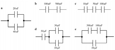
Charge stored by a capacitor Q = CV
Calculations of capacitance:
In parallel circuits CT = C1 + C2
In series circuits 1/CT = 1/C1 + 1/C2
For each circuit below, determine the total capacitance of the circuit
Section 3 - Electrical properties and uses of materials
Choose suitable examples of materials and their uses in order to provide an illustrated explanation of the properties of the following: conductivity, resistivity, insulators and conductors, ohmic and non-ohmic conductors, capacitors acting as filters in AC circuits and semi-conductors.
You will now test a variety of circuit components to show that the medical equipment will work properly.
Section 4 - Experiment 1: Ohmic and non-ohmic behaviour
Accurately construct a circuit with the following resistors (in turn) connected in series with a switch and power source: Constantan wire, a commercial resistor and a filament light bulb. Connect an ammeter and voltmeter and record the voltage and current over a range of values for voltage. Use a table to present your readings.
Plot graphs of voltage against current and interpret the graph to evaluate which resistors obey Ohm's Law and which do not. Apply Ohm's Law to predict the current for the commercial resistor at known voltages and compare the predicted values to your measured values. Make comments about the accuracy of your practical readings and any suggested improvements you would make to your practical.
Section 5 - Experiment 2: Resistance in series and parallel circuits
Use three resistors (100Ω, 200Ω and 300Ω) in series, parallel and combined circuits, by comparing measured values of voltage and resistance to your predicted values of voltage and resistance.
Accurately construct the circuits and take measurements, after your assessor has checked and confirmed your circuits are safe.
Measure the resistance of the individual resistors using an ohm setting on the multi-meter. Use these measurements to predict the theoretical value of the total resistance of the circuit.
For voltage outputs from the power pack of 1.0V- 6.0V in 1.0V steps, measure the current and record the results in a table.
Calculate the total resistance of the circuit at each voltage and compare it to predicted value of total resistance.
At a voltage output of 6.0V, measure potential difference across each resistor. Record any observations about the values you obtain.
Use your calculations and comparisons to evaluate the operation of your circuits. Include graphical representations for appropriate electrical relationships (e.g. resistance, power, charge) to support your evaluation.
Section 6 - Experiment 3: Capacitors in series and parallel circuits
Accurately construct simple circuits containing three capacitors and a power pack, firstly with the capacitors in series and then in parallel.
Take measurements of capacitance, after your assessor has checked and confirmed your circuits are safe.
Make a valid comment as to whether your measurements support the theory that the total capacitance in a parallel circuit is the total of the individual capacitance of each capacitor added together.
Make a valid comment as to whether your measurements support the theory that the total capacitance in a series circuit is less than the capacitance of any individual capacitor in the circuit.
Section 7 - Experiment 4: Potential divider circuit
Voltage dividers are widely used in electric meter circuits, where specific combinations of series resistors are used to "divide" a voltage into precise proportions as part of a voltage measurement device.
Research how to build voltage divider circuits and demonstrate through experiment how to divide a 6.0V power output into 1V, 2V and 3V using three resistors. Show your calculations (Kirchoff's laws) to predict what voltage you will get from your resistors, and then measure the actual voltage. Compare your predicted and measured values. Use your calculations and comparisons to evaluate the operation of your divider circuit. Your evaluation should consider the following:
Graphical representations for electrical relationships (e.g. resistance, power, charge)
Reliability of your results over a given range
Limitations of the investigation, and ways to improve future experimental work
Attachment:- Assignment Brief.rar