Reference no: EM13864321
Stability of Engineering Structures Spring
Subjects: Stability of cylindrical shells; design of beam-columns.
In this project we consider two very different problems. First, we design cylindrical shells subjected to hydrostatic pressure. We consider two possible modes of failure, i.e. the loss of stability and failure due to the loss of strength. The second part of the project deals with design of beam-columns. These structures subject to a combination of transverse and compressive loads do not become unstable in the classical sense, but they fail due to excessive deformations and stresses (i.e., the loss of strength).
Part 1
Design a submersible vehicle capable of operating at the maximum depth prescribed in the project. The vehicle represents a cylindrical shell with spheroidal ends caps (you do not have to design the caps). When subject to hydrostatic pressure, the caps transmit the axial force to the shell that is also loaded by lateral pressure.
Given: Design depth (it varies from 100m to 2,500m), length and outer radius of shell.
Your task: Choose the material (it has to be a metal), prescribe the required thickness of the shell.
Present the result in the form of the required thickness as a function of the design depth (vary the depth in 100 meter intervals from 100m to 2,500m). You must show the check for strength and stability and conclude which of these failure modes is critical for your design at various depths.
Modes of failure: Buckling, loss of strength.
Comments: Compare several metals as candidates for the vehicle and justify your choice. As is the case in real life, you have to find the material properties from published data or on the web. The weight of the vehicle is an important consideration. Thus, try to reduce it be able to increase the useful weight of equipment and cargo. Use the factor of safety equal to 1.0 for all failure modes (the design depth specified in your variant would be reduced by a certain factor to arrive at the operational depth: determining the operational depth is not a part of the project).
You can use the von Mises strength criterion. In case of a relatively thin cylindrical shell subject to hydrostatic pressure the through-the-thickness stresses can be neglected. Furthermore, due to symmetry, in-surface shear stress sis absent. Thus, the von Mises criterion becomes (Y=yield stress):
σ2x - σxσy + σ2y = Y2
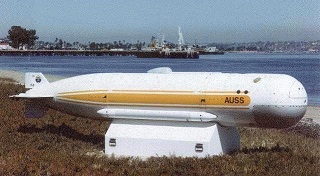
Example of a submersible vehicle:
The Advanced Unmanned Search System (AUSS)
From: https://www.spawar.navy.mil/robots/undersea/auss/auss.html
The center section is a cylindrical graphite epoxy pressure hull with titanium hemispherical ends. In our project we will assume that the hull is manufactured from an isotropic metal (rather than a composite material).

|
Variant
|
Length of shell (mm)
|
Outer radius of shell (mm)
|
|
1
|
10,000
|
1,000
|
|
2
|
3,000
|
1,200
|
|
3
|
5,000
|
1,000
|
|
4
|
8,000
|
1,600
|
|
5
|
7,000
|
1,700
|
|
6
|
10,000
|
950
|
|
7
|
1,000
|
600
|
|
8
|
6,000
|
800
|
|
9
|
7,000
|
1,000
|
|
10
|
4,000
|
800
|
|
11
|
5,000
|
2,000
|
|
12
|
9,000
|
1,800
|
|
13
|
8,000
|
2,000
|
|
14
|
1,000
|
500
|
|
15
|
6,000
|
1,000
|
|
16
|
10,000
|
1,000
|
|
17
|
7,000
|
1,500
|
|
18
|
5,000
|
2,500
|
|
19
|
3,000
|
1,000
|
|
20
|
4,000
|
850
|
|
21
|
2,500
|
1,000
|
|
22
|
5,000
|
1,000
|
|
23
|
6,000
|
1,500
|
|
24
|
4,500
|
1,200
|
|
25
|
2,500
|
1,000
|
|
26
|
6,500
|
1,000
|
|
27
|
8,000
|
1,700
|
|
28
|
5,500
|
1,500
|
|
29
|
9,000
|
2,500
|
|
30
|
3,000
|
1,250
|
Part 2
You have to redesign a simply supported beam subject to a simultaneous compression and uniform pressure. The original beam prescribed in your variant was designed against uniform pressure only. However, due to the change in operational requirements, the beam-column that you design must withstand the same pressure and compression equal to ½ buckling load of the original beam. Thus, a redesign is required. The redesigned beam-column must be as light as possible. Compare four different designs and suggest the best (lightest) solution.
Material of the element is structural steel A36 that has a specific weight 0.28 lb/in³ (7.8 g/cm³). A36 steel in plates, bars, and shapes with a thickness of less than 8 in (200 mm) has minimum yield strength of 36,000 psi (250 MPa).
Use the factor of safety equal to 2 in all calculations (it is applied to the yield strength to obtain the allowable stress).
Comments: Use welded I-beams of your choice or profiles from the following table if they satisfy the requirements. If you design a welded beam, maintain the width-to-thickness ratio in the flanges in the range from 10 to 25 (otherwise, the slender flange can buckle locally). Use the height-to-thickness ratio for the web should be from 20 to 70 (in this project we are more restrictive to the proportions of the web and flanges than in project 2). Avoid the height of the web exceeding 1/10 the length of the beam-column.
Notes and recommendations:
1. You do not have to check local buckling in this problem.
2. In general, the design will be lighter if you use high and slender webs and relatively "thick" flanges.
3. First, you have to determine uniform pressure that causes failure of the simply supported beam in your variant (consult handbooks or web, if necessary, to solve this simple bending problem). Next, you specify the buckling force for the same beam (assume that buckling can occur in the vertical plane only). Now you have the combination of pressure and compressive force that your redesigned beam should withstand.
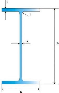
4. A schematic cross section of the beam is shown below. You do not have to account for rounded sections of radius r shown in the cross section in your computations of the area and moment of inertia (this effect is negligible).
In the following table, L = length of the beam and length of the redesigned beam column.
Beams according to the standard:
From: https://www.premco.eu/strona,symbol,profiles_WFB.html

|
Variant Type
|
L
|
h
|
b
|
s
|
t
|
r
|
mass of 1 meter
|
|
|
[m]
|
[mm]
|
[mm]
|
[mm]
|
[mm]
|
[mm]
|
[kg/m]
|
|
1 W 6x20
|
2.9
|
157
|
153
|
6.6
|
9.9
|
6
|
29.8
|
|
2 W 6x25
|
2.5
|
162
|
154
|
8.1
|
11.6
|
6
|
37.1
|
|
3 W 8x18
|
2.5
|
207
|
133
|
5.8
|
8.4
|
8
|
26.6
|
|
4 W 8x21
|
3.5
|
210
|
134
|
6.4
|
10.2
|
8
|
31.3
|
|
5 W 8x31
|
3.5
|
203
|
203
|
7.2
|
11
|
10
|
46.1
|
|
6 W 8x35
|
3.0
|
206
|
204
|
7.9
|
12.6
|
10
|
52
|
|
7 W 8x40
|
3.0
|
210
|
205
|
9.1
|
14.2
|
10
|
59
|
|
8 W 8x48
|
3.0
|
216
|
206
|
10.2
|
17.4
|
10
|
71
|
|
9 W 10x12
|
3.5
|
251
|
101
|
4.8
|
5.3
|
8
|
17.9
|
|
10 W 10x15
|
3.5
|
254
|
102
|
5.8
|
6.9
|
8
|
22.3
|
|
11 W 10x17
|
3.5
|
257
|
102
|
6.1
|
8.4
|
8
|
25.3
|
|
12 W 10x19
|
4.0
|
260
|
102
|
6.4
|
10
|
8
|
28.4
|
|
13 W 10x22
|
4.0
|
258
|
146
|
6.1
|
9.1
|
8
|
32.7
|
|
14 W 10x26
|
4.0
|
262
|
147
|
6.6
|
11.2
|
8
|
38.5
|
|
15 W 14x22
|
4.5
|
349
|
127
|
5.8
|
8.5
|
10
|
32.9
|
|
16 W 14x26
|
5.0
|
353
|
128
|
6.5
|
10.7
|
10
|
39
|
|
17 W 16x26
|
5.0
|
399
|
140
|
6.4
|
8.8
|
10
|
38.8
|
|
18 W 16x31
|
5.0
|
403
|
140
|
7
|
11.2
|
10
|
46.1
|
|
19 W 18x35
|
5.5
|
450
|
152
|
7.6
|
10.8
|
10
|
52
|
|
20 W 18x40
|
5.5
|
455
|
153
|
8
|
13.3
|
10
|
60
|
|
21 W 18x46
|
6.0
|
459
|
154
|
9.1
|
15.4
|
10
|
68
|
|
22 W 21x44
|
6.5
|
525
|
165
|
8.9
|
11.4
|
13
|
66
|
|
23 W 21x50
|
7.0
|
529
|
166
|
9.7
|
13.6
|
13
|
74
|
|
24 W 21x57
|
7.0
|
535
|
166
|
10.3
|
16.5
|
13
|
85
|
|
25 W 18x40
|
7.0
|
455
|
153
|
8
|
13.3
|
10
|
60
|
|
26 W 18x46
|
7.0
|
459
|
154
|
9.1
|
15.4
|
10
|
68
|
|
27 W 21x44
|
7.5
|
525
|
165
|
8.9
|
11.4
|
13
|
66
|
|
28 W 21x50
|
8.0
|
529
|
166
|
9.7
|
13.6
|
13
|
74
|
|
29 W 21x57
|
8.5
|
535
|
166
|
10.3
|
16.5
|
13
|
85
|
|
30 W 10x15
|
4.5
|
254
|
102
|
5.8
|
6.9
|
8
|
22.3
|