Reference no: EM13867176
Speed Control of a DC Motor
1 Objective:
The objective of this laboratory is to study and implement speed control of a dc motor.
2 Introduction:
One way to control the speed or angular position of a dc motor is an open-loop system as shown in Figure 1. In the open-loop case, the output will follow the desired function as long as the system remains constant. Any change in load, amplifier gain or other system parameters will cause a deviation from the desired output. In order for the motor to follow a desired function, regardless of system changes, a closed-loop system must be used as shown in Figure 2.
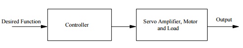
Figure 1. Open-loop control system.
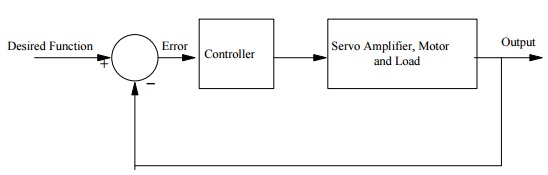
Figure 2: closed-loop control system.
In the closed-loop system, the output variable is measured, fed back and compared to the desired input function. Any difference between the two is a deviation from the desired result, and the difference is amplified and used to correct the error. In this manner, the closed loop system is relatively insensitive to system changes, and thus performs well in spite of them. However, now the response of the system depends on the closed-loop configuration and may be overdamped, underdamped, or even unstable. Special care must be taken in the design of closed-loop systems if the desired response is to be achieved.
In the velocity control, motor speed is required to follow a desired velocity profile. A general diagram is given in Figure 2 where the desired function is the voltage proportion to the desired velocity, and the output is the voltage proportional to actual velocity. The actual output can be obtained from the tachometer as shown in Figure 3.
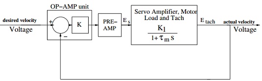
Figure 3: Velocity control of a dc servo motor
Ideally, if the forward path gain is high, only a small error signal is required to operate the motor, then the motor speed will be such that the tachometer voltage substantially equals the reference voltage, so that the speed is controlled by the reference voltage. In the experimental set-up, the operational amplifier discussed in Lab 2 is used to combine the function of a comparator and a variable gain.
3 Pre-Lab Assignment:
1. Use the transfer function Etach/Es found in Lab 4 and pre-amp gain of 10 and draw the Bode plot of the system shown in Figure 3 for K = 0.1, 1.0 and 1.5. Place all the plots on the same figure. Find the G.M., P.M. and the bandwidth of the system for different values of K. From the bandwidth, estimate the time constants. Also, find the steady-state error.
2. Now, determine the output of the system using MATLAB/Simulink for the above systems for a reference input of 0.25 volt. Place responses for the three values of K (given in part (1)) on the same plot. Find the time constants and compare these with the results found in part 1. Also, find the steady-state errors and compare the results with those obtained in part (1).
3. The transfer function of the servo amplifier, motor and load in figure 5.3 does not contain the electrical time consant. If the electrical time constant of the motor is 1.5 msec, what is the transfer function of the servo amplifier, motor and load block in Figure 3. Using this transfer function, draw the Bode plot for K=1.0. Find the B.W. and P.M. of the system and compare the results with the results obtained in part (1). Also, plot the response of the system to a reference input of 0.25 volt. Comment on the results.
4 In-Lab Procedure
On each lab workbench, there should be
1. a servo-amp (wired for armature control)
2. a motor unit
3. a tachometer/gearbox unit
4. a power supply
5. a brake
6. an op-amp (select external feedback)
7. an attenuator unit
8. a disk mounted on the armature extension shaft
Wire the system shown in figures 3 except do not connect the gearbox/tach unit yet. There are two pots on the attenuator unit. Wire one of these pot to provide the reference input (connect -15V to the high side and ground to low.) Use the second pot on the attenuator unit for the gain control. Connect the high side of this pot to the output of the op-amp and the low side to the ground. Wire the center tap to one of the input of the op-amp. With this pot set at full scale, the gain through the op-amp should be 1. Lowering the pot setting will increase the gain. Set the pot to maximum (10), and increase the setting of the reference pot. The speed of the motor should increase.
To use the tach voltage as feedback in this configuration, one side of the tach must be grounded and the other fed to one input of the op-amp. The voltage fed back must oppose the reference voltage (-ve feedback), so that when the two are equal, the error signal which drives the motor is zero. Run the motor at about 1000 rpm, and determine which side of the tach must be grounded so that the other side has a positive voltage. Wire this side to one input of the op-amp. The speed should fall.
1. Now, apply -0.25 volt to the system and obtain the responses of the system for K = 0.1, 1.0 and 1.5 . Find the time constants and steady-state errors. Compare the results to the theoretical result obtained in parts (2) and (3) of the pre-lab.
2. Now, apply the brake in increments of 10% and repeat part 1.
5 Report
Your report should contain plots of the time constants versus gain and the steady-state error versus gain for different values of brake scale. Explain your results.