Reference no: EM131557898
Lab Assignment
Objective:
To Study NPN transistor IN curves by:
• Simulating a transistor to investigate the collector current versus the collector-to-emitter voltage.
• Implementing a circuit and taking measurements of the IC vs. VCE curves.
Materials:
1. Laboratory setup, including breadboard
2. 1 NPN transistor (e.g., 2N2222)
3. Several wires and resistors of varying sizes
Part 1: Simulation:
Consider the circuit shown below.
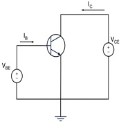
Enter the circuit into your simulator's schematic editor, applying DC voltage supplies to the base and to the collector of the transistor.
IC vs.VBE
• While setting VCE to a constant value of 5V, sweep the base voltage from 0V to 0.8V in increments of 0.1 V. Plot a curve of IC vs. VBE and place the plot in your lab writeup.
• At what value of VBE does current begin to conduct?
• What are the values of IB and IC when VBE: 0.7V?
• Based on these numbers, what is your estimate of β?
IC vs. VCE
• For three values of VBE (0.6 V, 0.7 V. and 0.8 V), sweep the collector voltage from 0V to 2V in increments of 0.1 V. Plot the curves for IC vs. VCE, using a graphing program indicating the value of VBE; next to each curve.
• What observations can be made about the curves?
Part 2: Measurements:
Assemble the circuit from the figure above, using a power supply to generate the DC voltages.
IC vs. VBE
• While setting VCE to a constant of 5 V. sweep the base voltage from0 to 0.8V in increments of 0.1V, and measure the collector current using the power supply. (Note that not all power supplies allow you to accurately measure current. It this is the case for your lab setup, you place a small resistor in series with the collector and measure the voltage drop across the resistor.)
• Plot a curve of IC vs VBE
• At what value of VBE does the current turn on?
• Using a small resistor placed in series with the base and collector terminals, measure IB and IC for VBE = 0.7V
• Based on these numbers, what is your 3?
IC VS. VCE
• For three values of VBE (0.6 V, 0.7 V, and 0.8 V), sweep the VCE from 0 V to 1 V in increments of 0.1 V, and measure the collector current using the power supply.
• Plot the curves for IC vs. VCE using a graphing program and clearly indicating the value of next to each curve.
Part 3: Post-Measurement Exercise:
Simulation vs. Measurement
• What are the main differences between your simulated and measured curves? Can you explain the differences?
Early voltage, VA
• Based on your simulated IC vs. VCE curves for an active transistor, extract the Early voltage VA.
• Does VA change significantly for each value of VBE?
• What is the average value of VA?
Part 4: Design and Simulation
Consider the circuit shown below.
Design the circuit such that IC = 1mA, VB = 0, and VC = +5V. Use supplies of V+ = V- = 15V. Although there will be variations tram transistor to transistor, you may assume a value 100 for β in your calculations. Also assume that VBE = 0.7V.
In your lab writeup, perform the following.
Hand Calculations
• What are lB and 1E? Based on these numbers, what is VE?
• You now have enough information to calculate RC and RC. Are the calculated values available in your kit? Can you achieve these values by combining several resistors? Comment.
• Derive the Thevenin equivalent of R1 and R2. What values of R1 and do you need to use to achieve VB = 0 V? Remember that IB ≠ 0. Is the problem completely specified? If not, what needs to be specified?
Simulations
• Simulate your circuit using values of RE, RC, R1, and R2 based on you r calculations.
• Report the values of VE, VC, VB, IC, and IB. How closely do they match your calculations? (Remember: The simulator has its own, more complex model of the real transistor, so there should be some small variations.)
Prototyping and Measurement
• Assemble the circuit onto a breadboard.
• Using a digital multimeter, measure VE,VC, and VB.
• Using a digital multimeter, measure all resistors to three significant digits.
Post-Measurement Exercise
• What are the measured values of VBE and VCE? How do they compare to your pre-lab calculations? Explain any discrepancies.
• Based on the measured values of VC and VE and your measured resistor values, what are the measured values of IB, IC and IE based on your lab measurements?
Part 5: NPN in Saturation Mode:
Hand Calculations
• Based on the specifications, calculate VE and VB.
• You now have enough information to calculate RC and RE. Are the calculated values available in your kit? Can you achieve this value by combining several resistors? Comment.
• What is βforced?
• What values of R1 and R2 do you need to use? Is the problem in completely specified?
Simulation
• Simulate your circuit using values of RE, RC, R1 and R2 based on your calculations.
• Report the values of VE, VC, VE, IE, IC, and IB. How closely do they match your calculations?
Part 6:Post-Measurement Exercise:
Prototyping and Measurement
• Assemble the circuit onto a breadboard.
• Using your volt multimeter, measure VE, VC and VB. Report them in your lab writeup.
• Using a digital multimeter, measure all resistors to three significant digits.
Post-Measurement Exercise
• What are the measured values of VBE and VCE? How do they compare to your pre-lab calculations? Explain any discrepancies.
• Based on the measured voltages and resistor values, what are the measured values of IB, IC and IE, based on your lab measurements? What is βforced?