Reference no: EM13892422 , Length: 6
Analyze and design a boost converter and its controller given the following specifications:
An input voltage of 20V < Vin < 30V and an output of Vout = 50V over a load range of 10W < Pout < 100W. Switching frequency is fsw = 250kHz.
Hardware Design
1) Design the inductor (L) and capacitor (C). The current ripple ΔiL should be below 5% of the average inductor current IL at the maximum load under any Vin. The steady state ripple ΔVout is below 2% of the steady-state value of the output voltage. For the designed L, find the value of Iout,crit at the boundary of DCM and CCM. Plot Iout,crit vs. Vin.
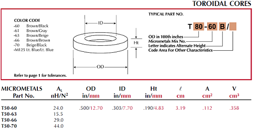
2) For designed L, suppose there are four cores available listed below, select the core size to use the space maximum, design the inductor's number of turns N and the wire (use American wire gauge table) size.
Steady-state Analysis
3) Analytically determine and draw the expected current and voltage waveforms for each component in your circuit at both light and heavy load.
4) Using PSpice/Matlab software, simulate the circuit under the heavy and light load conditions (provide schematic of the whole system). Plot the voltage and current of each component within 3 to 5 switching periods in the steady-state. Validate that the output of your simulation matches your analytical calculations in (2).
Modeling and Controller Design
5) Based on your designed circuit, considering the parasite resistance of the inductor r is 0.2Ω, using the average state-space method and small-signal technique to the transfer function v~o(s)/d~(s). Draw the open-loop bode plot of the frequency response (with matlab/pspice, not hand drawing).
6) Design a proportional-integral (PI) controller (recommend to use matlab siso toolbox) so that phase margin of the loop transfer function should be over 35o, and the crossover frequency is no larger than 10kHz. Provide the close loop bode plot (with matlab/pspice).
System Simulation
7) Using PSpice/Matlab software, simulate the designed circuit with controller, 1) Vin = 25 + 5*sin(2Π*60*t), simulate output voltage vo which should be a constant value, plot both Vin and vo in a same figure with time range more than 16.7ms; 2) measure the dynamic of the output voltage together with the disturbance of input or load through designing disturbances in load and input voltage. a) input voltage disturbances: Vin step change from 20V to 30 V; 2) load change from 10W to 100W. [Plot the disturbance, i.e., Vin, Load, and the output voltage of the converter in a same figure]
Write a report that documents that describes your results and observations from parts (1)-(7). Make sure all plots are well labeled and that explanations contain solid analytical foundations.
Make sure the figures are organized, neat and easy to be read and they are drawn by the software not by hand. Do NOT plot one graph per page.
|
Symantec narrowing its operations
: Many are skeptical because they feel this move corners business and doesn't allow for diversity, will investors take a hit with Symantec narrowing its operations?
|
|
How do the adults in melba family respond to the incident
: In 1954, when Melba is just thirteen, a white man tries to rape her. How do the adults in Melba's family respond to the incident? Why do you think they decide not to call the police? What do they fear
|
|
Which organizational model would you most prefer to work in
: Which organizational model would you most prefer to work in? Support your choice by discussing strengths and weaknesses that are inherent in these organizational models.
|
|
Should the drugs be rationed in any way, to keep costs down
: Select an ethical issue such as one of those described above and provide a pro/con comparison of related to the ethics of payment.
|
|
Simulate the designed circuit with controller
: Design a proportional-integral (PI) controller (recommend to use matlab siso toolbox) so that phase margin of the loop transfer function should be over 35o, and the crossover frequency is no larger than 10kHz - Analytically determine and draw t..
|
|
Briefly describe a systems implementation scenario
: Briefly describe a systems implementation scenario (actual or fictitious) that illustrates a failure to adequately consider all options and condition, along with the respective implications.
|
|
Prepare a ppt on lenovo pc acquiring ibm
: Prepare a PPT on Lenovo(PC) acquiring IBM. Consider the following points in your ppt. Business overview, STOCK ANALYSIS, Target Company SELECTION and Acquisition Synergies.
|
|
Should government regulate art and is it even possible
: Throughout theatre history, governments and other governing institutions have attempted to regulate theatre (limiting producing companies, the number of productions or withholding funding). Should government regulate art? Is it even possible? Rat..
|
|
Why are operations plans and organizational budgets
: What value, if any, do financial management and budgeting have for accountability and control of public health organizations? Most marketing business professionals would agree that effective marketing messages should be clear, consistent, and compell..
|