Reference no: EM132933911
ELEC2102 Digital Electronics
Traffic Light Junction Simulator Assignment
Specifications
You will be required to design and simulate a typical Traffic Light Junction controller. You will be using National Instruments MultiSim 10 Circuit-Design Suite for that purpose.
The junction is shown below:
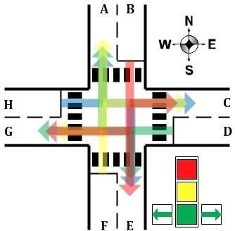
• All traffic moving along lanes B, D, F and H have the possibility of turning left, right or heading straight at the junction.
• The traffic signals is of the type shown above and there are 4 of those on the left-side of lanes B, D, F and H.
• The central lights are for straight traffic only, the left and right Green lights are for left and right traffic only. The left and right Green lights are ON simultaneously for the same duration and during that time the central Yellow light is ON, indicating no straight traffic flow.
• The central red light means no traffic is possible in any direction.
• There are Green WALK lights on each ends of the 4 pedestrian crossings. When the Green WALK lights are OFF, pedestrians should NOT cross. Note: There are no push buttons.
• For straight traffic, Red stays ON for 40 seconds, Yellow for 8 seconds and Green for 16 seconds.
• The left and right Green lights are ON for 8 seconds only (i.e. when central Yellow is ON) otherwise they are OFF for 56 seconds.
• The Green WALK lights on each side of a road are ON for 16 seconds and OFF for 48 seconds.
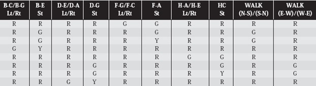
To give you a big head start, all the 8 possible simultaneous lights conditions are given in the table below:
Tasks
1. Depict the eight simultaneous possible lights conditions above using three binary outputs, say, X, Y and Z. Derive the boolean expressions in terms of X, Y and Z for all the possible lights conditions. (Hint: It should reduce down to 18)
2. Design the circuit using a 555 Timer and suitable Counter IC, logic gates and LEDs to act as the traffic lights. Give suitable values for the external R-C values for the 555 Timer and other relevant components.
3. Replace the logic gates to provide an all IC based-solution.
4. Finally, simulate your design to test the proper functioning of your system.