Reference no: EM132900160
There is a power transmission system shown in the following Figure 1. This system is designed to transmit power, P, from an AC motor at speed of ωAC to a driven pulley using a belt. The power then is transmitted to the gear box with ratio ωshaft1/ωshaft2 of and finally transmitted to the output shaft.
You must design one of the following: (i) belt, (ii) shaft and gears, or (iii) bearings and gears, depending on the last digit of your student ID. For example, if your student ID is 218608729., [hen you must design bearings and gears in (iii).
The information that you must provide is given in the tables below. The details of the calculation should be presented in the submission file and the final answers should be inserted in the designated table. The marks will be given mainly based on the final answer while there is mark for details of the calculations as well, Calculations can be hand-written or typed. If they are hand-written, you must ensure that they are clear and caii be easily understood.
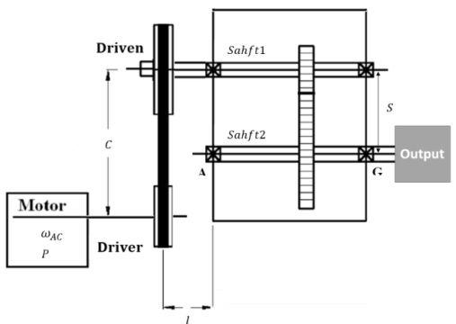
Figure 1: Schematic of power transmission system for Machine Elements Mini Project
(i) Shaft and gear design
A gear train should be designed to reduce the speed from Shaft1 to Shaft2 with ratio ωshaft1/ωshaft2 = 2.5. The gears on Shaft1 and Shaft2 have the same Diametral pitch. P = 6, pressure angle θ = 20 deg, and 20 and 50 teeth. respectively. Assume the ultimate shear stress for the shafts as 370 MPa and a factor of safety as 2. Using the appropriate formula and the tables find the followings:
(a) The distance between the Shaft 1 and Shaft2. S (mm),
(b) The critical bending moment along the Shaft2 (N.m),
(c) The minimum diameter of solid Shaft2, Dshaft2,
Show your calculations and include your final answer clearly, by providing the following table in your report.
|
(a)
|
S (mm)
|
|
|
(b)
|
MShaft2 (N.m)
|
|
|
(c)
|
Dshaft2
|
|
(ii) Machine elements calculations in your- project: For all students.
Please include a small section that describes now you have applied the machine elements calculations that you have learned in SEM200 in your project. This is just a brief description to demonstrate that you know how to apply this theory into a real project. in this section, we will not be assessing the details of the calculations. We are focussed on you being able to demonstrate the process of how and where the calculations have been used to inform the design of your team's machine, Your description may include some equations and values to assist your explanation, but the full details of the calculations should not be provided, as these will not be assessed.
If these calculations have been used extensively in your project, then you may choose 2 to 3 examples of the calculations that best demonstrate your understanding.
Attachment:- power transmission system.rar