Reference no: EM132585201
SEN728 Transportation Infrastructure Systems - Deakin University
Learning Outcome 1: In this assessment task, students investigate for creative and innovative approaches to analyse complex transportation problems related to air and public transportation
Learning Outcome 2: In this assessment task, students evaluate transportation, economic, social and environmental impacts of air and public transport projects
PART A: BUS ROUTE PLANNING AND ANALYSIS
In Geelong City Centre, a bus route of 15 stops is currently being planned which will be served by a single-decker bus with seating capacity of 50 passengers. Passengers will board the bus from the front door and alight through the back door. When passengers board and alight the bus, they will tap their Myki card to card readers for making fare payments. The route runs in mixed-traffic lanes where buses are allowed to use the lane adjacent to the bus lane.
The travel time (in minutes) between two consecutive stops in each direction of movement are estimated using journey time data obtained from 30 days. The average travel times between two consecutive stops are given in Table 1.
Table 1: Travel time between stops in both way journeys
|
Journey 1: Travel from Stop 1 to Stop 15
|
|
From Stop
|
1
|
2
|
3
|
4
|
5
|
6
|
7
|
8
|
9
|
10
|
11
|
12
|
13
|
14
|
|
To Stop
|
2
|
3
|
4
|
5
|
6
|
7
|
8
|
9
|
10
|
11
|
12
|
13
|
14
|
15
|
|
Travel time (mins)*
|
5
|
6
|
7
|
5
|
6
|
6
|
4
|
4
|
4
|
5
|
5
|
5
|
6
|
6
|
|
Journey 2: Travel from Stop 15 to Stop 1
|
|
From Stop
|
15
|
14
|
13
|
12
|
11
|
10
|
9
|
8
|
7
|
6
|
5
|
4
|
3
|
2
|
|
To Stop
|
14
|
13
|
12
|
11
|
10
|
9
|
8
|
7
|
6
|
5
|
4
|
3
|
2
|
1
|
|
Travel time (mins)*
|
6
|
6
|
5
|
6
|
4
|
4
|
4
|
4
|
6
|
6
|
6
|
6
|
6
|
5
|
* the travel times are inclusive of the time periods the buses would spend at stops for passenger boarding and alighting
For Journey 1, the ridership of the route is estimated from a survey or bus users, see Table 2. It was noted in the survey that there are some regular passengers boarding at Stop 4 (2 out of the 16 passengers boarding at this stop) and alighting at stop 9 (2 out of the 17 passengers alighting at this stop) who require 5 sec/passenger extra boarding time and 6 sec/passenger extra alighting time.
Table 2: Number of alighting and boarding passengers at each stop in Journey 1
|
Stop No.
|
1
|
2
|
3
|
4
|
5
|
6
|
7
|
8
|
9
|
10
|
11
|
12
|
13
|
14
|
15
|
|
Alighting passengers
|
0
|
5
|
8
|
8
|
8
|
9
|
14
|
19
|
17
|
17
|
16
|
12
|
8
|
8
|
7
|
|
Boarding
passengers
|
21
|
19
|
16
|
16
|
10
|
10
|
14
|
15
|
10
|
10
|
10
|
2
|
4
|
0
|
0
|
Furthermore, the following data are known
• Boarding time = 2.5 sec/passenger when no passengers are standing,
• Boarding time increases to 3 sec/passenger if there is at least one passenger standing,
• Alighting time = 2.5 sec/passenger
• Headways between buses to be maintained = 15min
• Door opening and closing time = 4 sec (2 sec for opening and 2 sec for closing)
• Minimum layovers are 10min at each end and 15% of running time (total both layover), which is greater
Task 1: Prepare a route schedule for the bus route (covering both way journeys) to cover the time block from 7:00am to 10:00am, if it is required that the first bus in both directions of travel should leave at 7:00am or earlier. Present the route schedule in a tabulated form by clearly indicating the departing times at the stops in both way journeys. Present your results with detailed calculation steps. Make any other reasonable assumptions, if needed, with justifications.
Task 2: Determine the i) the critical bus stop in the route, ii) dwell time in each stop, and iii) passenger load factor in each stop. Present your results with detailed calculation steps. Make any reasonable assumptions, if needed, with justifications.
Task 3: Suppose that the critical bus stop determined earlier is an on-line nearside type bus stop which has 2 berths of loading areas, loading area capacity of 26 buses, bus stop capacity of 48 buses/bus-stop/h, and the ratio of curb lane traffic volume to curb lane capacity is 0.6. Using the data given, determine the capacity of the bus lane. Present your results with detailed calculation steps. Make any other reasonable assumptions, if needed, with justifications.
PART B: RAIL ROUTE DESIGN AND ANALYSIS
Suppose that you have been commissioned to design a rail route with a single rail track of gauge 5ft 3inch between points A and E, as shown in Figure 1 (vertical profile) and Figure 2 (Horizontal profile). Note that Tables 3 and 4 provide the stations, elevations, vertical grades of the route.
Table 3: Stations and Elevations at Route Points
|
Points
|
Station (ft)
|
Elevation (ft)
|
|
A
|
1 + 00.00
|
Not measured
|
|
B
|
5 + 00.00
|
150 ft
|
|
C
|
9 + 00.00
|
Not measured
|
|
D
|
10 + 00.00
|
Not measured
|
|
E
|
13 + 00.00
|
Not measured
|
|
F
|
33 + 00.00
|
Not measured
|
|
G
|
36 + 00.00
|
Not measured
|
Table 4: Vertical grades of route sections
|
Route section
|
Vertical grade
|
|
A-B
|
-1%
|
|
B-C
|
+1.2%
|
|
C-D
|
0%
|
|
D-E
|
-0.75%
|
|
E-F
|
-0.75%
|
|
F-G
|
-0.75%
|
Figure 1: Vertical profile of the rail route

Figure 2: Horizontal profile of the rail route
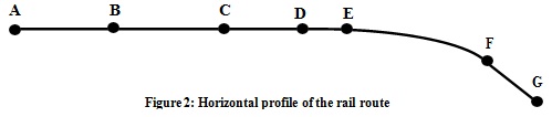
Task 4: Suppose that a vertical curve of length 600ft exists somewhere in the route section A to
C. Consider Point B as the PVI of the curve which has an elevation of 150ft. Determine the stations and elevations at BVC and EVC of the curve. In addition, calculate the elevation on tangent at stations (4 + 00.00) and (5 + 50.00). Present your results with a detailed calculation steps. Make any other reasonable assumptions, if needed, with justifications.
Task 5: Between the points E and F, there exist a simple circular curve of radius 1640ft with a design speed of 40 mph. Note that the route sections A-E and E-F are straight sections. Design the superelevation required at the curve if a minimum ramping rate of 1 in 720 is to be used. Determine the elevations of the inner and outer rails at the points TS, SC, CS, and ST of the horizontal curve. Present your results with a detailed calculation steps. Make any other reasonable assumptions, if needed, with justifications.
PART C: AIRPORT PLANNING AND DESIGN
Task 6: Planning runway orientation
You are asked to determine the orientation of a runway using the wind data provided in Table 5.
Table 5: Percent of time wind in each direction
|
Direction
|
4-15 mph
|
16-30 mph
|
31-45 mph
|
|
N
|
4.8
|
1.3
|
0.1
|
|
NNE
|
3.7
|
0.8
|
0
|
|
NE
|
1.5
|
0.1
|
0
|
|
ENE
|
2.3
|
0.3
|
0
|
|
E
|
2.4
|
0.4
|
0
|
|
ESE
|
5.0
|
1.1
|
0
|
|
SE
|
6.4
|
3.2
|
0.1
|
|
SSE
|
7.3
|
7.7
|
0.3
|
|
S
|
4.4
|
2.2
|
0.1
|
|
SSW
|
2.6
|
0.9
|
0
|
|
SW
|
1.6
|
0.1
|
0
|
|
WSW
|
3.1
|
0.4
|
0
|
|
W
|
1.9
|
0.3
|
0
|
|
WNW
|
5.8
|
2.6
|
0.2
|
|
NW
|
4.8
|
2.4
|
0.2
|
|
NNW
|
7.8
|
4.9
|
0.3
|
|
Total
|
65.4
|
28.7
|
1.3
|
Using the data tabulated above, draw a Type II wind rose diagram, showing % times of wind from each of the 16 directions and the four categories of wind speed (<=4 mph, 4-15 mph, 16-30 mph, and 31-45 mph). Using the wind rose, identify the orientation of single runway and present its bearings. Comment if it is possible to have a second runway, if yes, present its bearings.
Task 7: Airport configuration
For the airports shown in the below Figure 3 (higher resolution image is available in the Unit Site), identify the following items:
i. Runway - label the runway(s) on the image, state the type for each of the runway(s)
ii. Taxiway - label the taxiway(s) on the image, state the type for each of the taxiway(s)
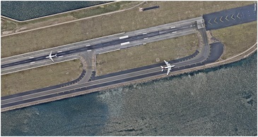
On the Figure 4 showing one end of a runway, clearly label the different types of pavement markings on the runway. Briefly explain what the text "34 L" means.
Figure 3: Airport configuration 1 (Melbourne Airport)
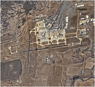
Figure 4: Runway markings (Sydney Airport)
Attachment:- Transportation Infrastructure Systems.rar