Reference no: EM132896100
SEM712 Introduction to Finite Element - Deakin University
Analysis Assignment
PART A - Theory
Question 1. Beam Elements
This question consists of multiple sub-questions. Please answer all questions.
For the following frame structure consisting of two parallel cantilever beams connected by spring with applied load P acting on node 2:
(a) Calculate the stiffness matrix of each member
(b) Assemble the elements and calculate the stiffness matrix of the structure
(c) Apply the effect of the supports and then calculate the stiffness matrix corresponding to the free degrees of freedom
(d) Comment on how you would find the unknown deflection and rotational degrees of freedom at the nodes. DO NOT CALCULATE IT!
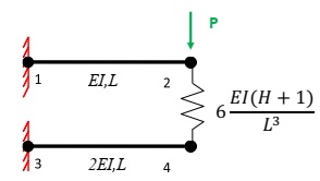
where H refers to your student number (second last digit).
Question 2. Plane Stress Elements
This question consists of multiple sub-questions. Please answer all questions.
An isoparametric four-node plane stress (CPS4) element is shown in Figure 1.
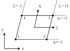
Figure 1: Geometrical representation of a 2D plane stress element
The co-ordinates of the nodes for the plane stress element are shown below in Table 1.
Table 1: Nodal co-ordinates for the isoparametric (CPS4) element
|
Node Number
|
(x,y) co-ordinates
(mm)
|
|
1
|
(-2,-2)
|
|
2
|
(1,-2)
|
|
3
|
(3,H)
|
|
4
|
(0,H)
|
where H refers to your student number (second last digit).
a) What is the purpose of the Jacobian matrix when deriving the stiffness matrix of an element?
b) For the element shown in Figure 3 and the coordinates given in Table 1, evaluate 1) ∂x/∂ξ
2) ∂y/∂ξ
3) ∂x/∂η
4) ∂y/∂η
c) Evaluate the determinant of the Jacobian matrix using your answers in part (b).
Question 3. General understanding & Numerical Integration
This question consists of multiple sub-questions. Please answer all questions.
a) The complete finite element equation system has three characteristic parts: The stiffness matrix; the solution vector; and the right-hand-side vector. What property does the stiffness matrix have before the essential boundary conditions are applied?
b) Name two characteristic differences between truss and beam elements.
c) Name 2 reasons for nonlinearities in finite element methods.
d) Numerical Integration
• Solve the following integral analytically to obtain the exact solution ∫-11 Fξ2 + Gξ + H dξ where
F, G and H refer to your student number. (1 point)
• Solve the integral using 1 Gauss integration point. (1 point)
• Solve the integral using 2 Gauss integration points. (1 point)
• Discuss the accuracy of your answers calculated by Gauss integration in comparison with the analytical result. Explain any inaccuracies.
Question 4. Complex boundary conditions and constraints
This question consists of multiple sub-questions. Please answer all questions.
The structure shown in Figure 2 has 4 nodes and 3 one dimensional truss elements.
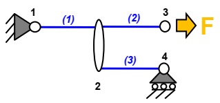
Figure 2: 1D Truss assembly with boundary conditions
The following displacement constraint exists:
u3 = Hu4
where H refers to your student number (second last digit).
a) For this constraint, which node would you choose as the master and which is the slave? Explain your decision.
b) To apply the multiple point constraint, you need to utilise the following transformation:
u = Tu^ k^= (TTKT)
Construct the transformation matrix, T, for the problem shown in Figure 4 to apply the constraint shown above. Ensure that you clearly state the size of the transformation matrix, T.
c) Explain the difference between C0 and C1 elements. Your answer should discuss the characteristics for these element types and how these relate to the Finite Element Method.
d) Explain why a B33 element performs well under bending by commenting on the order of shape functions.
Question 5. Problems in FEA
Suppose that a simulated structure using 2D rectangular plane stress elements is subjected to pure bending moment, see Figure 3a) below. A typical element of length a and height b experiences rigid body displacement/rotation plus a displacement field shown below in Figure 3b):
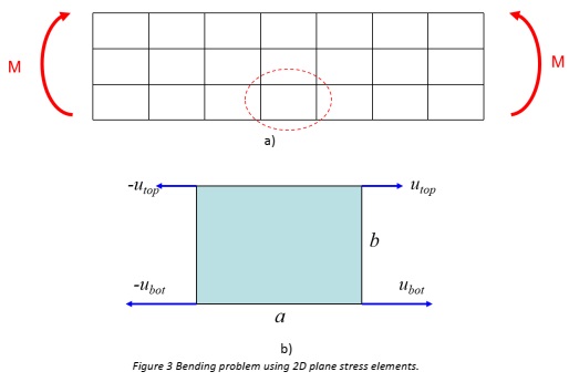
a) Express the displacement field (vertical and horizontal) in the depicted quadrilateral element in Figure b) with the given nodal displacements. Use linear shape functions in isoparametric coordinates.
b) Show that the strain components are
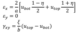
c) Comment on the result with respect to the shear strain.
d) What phenomenon is described here and how can you prevent it in finite element formulations.
PART B - Modelling
Question 6. Stress concentration in a plate structure
This question consists of multiple sub-questions. Please answer all questions.
A plate, shown in Figure 4, consists of two plates of material bonded by a thin layer of adhesive. The plate is clamped at one end and loaded by a corner force at the far end.
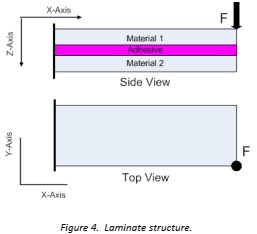
(a) Can symmetry be exploited to simplify the problem? Justify your answer.
(b) You are interested in the maximum corner deflection under the applied load. Explain your boundary and loading conditions for the problem in terms of the given coordinate system.
For this problem, the following three assumptions apply:
• the plate is very thin compared to the length and width,
• the adhesive layer does not influence the bending stiffness and can be neglected
• material 1 and material 2 are identical.
(c) What element type would you use to most efficiently model this problem? Justify your answer.
(d) Sketch a suitable mesh to determine the maximum in-plane stresses. Explain the features of your mesh in terms of the element formulation.
(e) The adhesive supplier has asked you to evaluate the maximum through-thickness stresses (σz) for the plate under bending to check that the selected adhesive is suitable for the job. Material 1 and 2 are now different. What type of elements do you recommend for the problem? Justify your choice.
Question 7. Structural analysis of a cantilever structure
This question consists of multiple sub-questions. Please answer all questions.
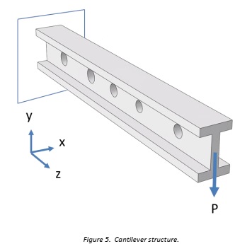
You are a Structural Engineer in a consultancy firm that has been tasked with analysing the structure shown in Figure 5. The client requires you to analyse the structure under two key load cases:
• Load case 1: vibration (eigenvalue)
• Load case 2: static stress
For the vibration analysis you must analyse the free vibration of the structure and do not need to consider the applied load. For the deflection and stress analysis you must consider the load applied to the free end of the beam (NOTE: load applied vertically down in the y direction at the centroid of the section).
Load case 1: Vibration
The holes presented in the structure are not expected to significantly affect the vibration properties.
(a) What element type should be used to most efficiently model the structure to calculate the first 6 modes of vibration?
(b) List the material properties required by ABAQUS for a vibration analysis.
(c) Comment on the number of elements required to calculate the first 6 natural modes of vibration to obtain accurate results. What feature of the element determines this number?
Load case 2: Static Stress
(d) Provide a sketch of the deformed geometry due to the applied force. Based on your experience at what locations would you expect the maximum stress?
(e) What two conditions must be true for symmetry boundary conditions to be applied to a problem?
(f) Considering symmetry, what is the minimum part of the structure required to be modelled in order to obtain a valid solution?
(g) What element type would you use in order to analyse the through thickness shear stresses (TXZ, TYZ)? Comment on the order of this element's shape function and its suitability to predict these shear stresses. For the given element type how many elements, through-the-thickness, are required for an adequate stress prediction?
(h) In a Finite Element simulation where are the stresses calculated in the element?
(i) How can you accurately extract surface stresses from a FE simulation? Justify your answer.
(j) Explain two ways to verify that your results are mesh independent.
(k) The client has provided an IGES file of the structure. Explain what an IGES file is and why it is useful.