Schematic entry and simulation of a full adder

Assignment Help Electrical Engineering
Reference no: EM13342725

Task1:  Schematic Entry and Simulation of a Full Adder

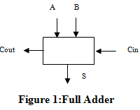
A full adder is a circuit that adds 2 bits and a carry.  The circuit takes three inputs, two data bits (A and B) and a carry bit (Cin), and outputs their sum (S) and a carry out (Cout) See Figure1.  For example, if A = 1, B = 0 and Cin = 1 then S = 0 and Cout = 1. 
1332_Simulation of a Full Adder.png

Enter a design for a full adder in Logic Works/SimAid. Simulate it using Logic Works and make sure it works as it is supposed to.  Turn in a print out of the circuit  logic diagram and of the full-adder

Task 2: Design of a 4-bit cascaded adder

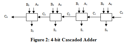
In this task, you are to design an N-bit binary adder by cascading N Full Adders in series.  The idea is to have the adder mimic the way we do addition with pencil and paper.  When we do addition with paper and pencil, we start from the LSB (least-significant bit) column, add each pair of bits in sequence and add the carry from one column of bits to the sum of the column to its left.  In other words, we form the ith sum Si by adding the pair of bits in the ith column and the carry-out from (i-1)st column.  We can therefore get the sum at each column by using a Full Adder circuit.  The sum of two N-bit numbers can be obtained by cascading a series of N Full Adders. Figure 2 shows a block diagram of a 4-bit adder
2427_Simulation of a Full Adder1.png

The multi-bit adder described is usually called a cascaded adder or a ripple-carry adder (because the carry ripples from one column to the next).  The method described above of cascading single bit building blocks (called bit slices) to form multi-bit operations is very common is digital design.  Its benefits are obvious: it allows us to build a complex circuit that realizes a complex function by replicating the same simple circuit N times, cutting down on design and implementation costs.

1) To what value should the LSB carry, C0, be set?

2) Design a 4-bit cascaded adder.

3) Create a new device symbol for the Full Adder and save it.

4) Use the Full Adder component to build the 4-bit cascaded adder. Simulate you circuit in Logic Works and test it.

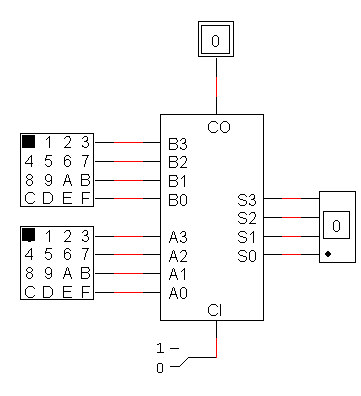
5) Create a new device symbol for the 4-bit cascaded adder.  Demo its operation using hex-keyboards and a hex display device (see diagram of figure 3 below).

6) Turn-in a printout of your design and of the test data used to test the circuit.  Note:  you need to have the test data ready for the demo.
1670_Simulation of a Full Adder2.png

Figure 3

Reference no: EM13342725

Questions Cloud

Define counterclockwise rotation as positive : An engine flywheel initially rotates counterclockwise at 5.03 rotations per second. Define counterclockwise rotation as positive
Consider the levels of control : Advise Polaris Ltd whether it is required to produce consolidated financial statements (CFS). Consider the levels of control and the members' rights in your answer.
What is the weight of the object : A solid steel cylinder is standing (on one of its ends) vertically on the floor. The length of the cylinder is 3.5 m and its radius is 64 cm. What is the weight of the object
Explain potentially useful information : Using the Nernst equation calculate the cell voltage for: Fe(s) + Cd2+(aq) ? Fe2+(aq) + Cd(s) when the [Fe2+] = 0.17 M and [Cd2+] = 1.1 M. Potentially useful information: Fe2+ + 2e
Schematic entry and simulation of a full adder : Enter a design for a full adder in Logic Works/SimAid. Simulate it using Logic Works and make sure it works as it is supposed to. Turn in a print out of the circuit logic diagram and of the full-adder
Find the entropy change of the universe in both cases : Suppose that the specific heat capacity cp Of the body discussed in Section 7.6 of the text is 10 J kg-1 K-1and T1 =200 K. Find the entropy change of the universe in both cases
Depict fischer projection formulas for the products : Draw Fischer projection formulas for the products likely to be obtained from the bromination of (Z)-2-pentene with Br2/acetic acid.
Develop a plan that highlights a creative growth concept : Develop a plan that highlights a creative growth concept
Find its first three overtone frequencies : A 3.62m long organ pipe is open on both ends. the fundamental frequency is 47Hz, and Find its first three overtone frequencies

Reviews

Write a Review

Electrical Engineering Questions & Answers

  Lithium ion battery technology

The paper includes Lithium ion battery technology with its advantages and disadvantages. The paper discusses about the Lithium air battery in which detailed reactions of Lithium with air including nonaqueous as well as aqueous are given.

  Power transformers and tariffs

Construction of different types of power transformer, significant energy savings

  Paper on orthogonal frequency-division multiplexing

This document is shown a paper on Orthogonal frequency-division multiplexing with advantages, disadvantages and uses.

  Function of the hmi in a scada system

This assignment contains electronics engineering questions like State the commonly found components of a SCADA (Supervisory control and data acquisition) system. and decribe the function of the HMI in a SCADA system.

  Resultant waveform of the odd harmonic series

Prepare an Excel graph showing the individual components and summated resultant waveform of the odd harmonic series resulting in an approximate square wave.

  Explain scada system

Explain the function of the HMI in a SCADA system.

  Design a 2-digit 24 second shot-clock

Design a 2-digit 24 second "shot-clock" countdown timer with pushbutton controller.

  Model a discrete-time system

To understand di erent signal models To be able to model a discrete-time system and design simple signal processing algorithms.

  Draw a relay construction diagram

Draw a relay construction diagram and briefly explain the operation of a relay.

  Frequency division multiplexing

Write a short technical report on Frequency Division Multiplexing

  Impact of electron energy

Briefly discuss the impact of electron energy, electron current and target on the Bremsstrahlung generated.

  Traffic light controller

The schematic of the traffic light controller

Free Assignment Quote

Assured A++ Grade

Get guaranteed satisfaction & time on delivery in every assignment order you paid with us! We ensure premium quality solution document along with free turntin report!

All rights reserved! Copyrights ©2019-2020 ExpertsMind IT Educational Pvt Ltd