Reference no: EM133095817
Question 1
Figure 1 shows a slotted link which forms a connection in a particular machine. A pin at B fits in the slot with its longitudinal axis in the z direction and centred at B. This pin imposes a total force of up to 190 N acting towards the inner quadrant surface, C. This force is uniformly distributed as a pressure on the upper inner quadrant surface, as depicted by the arrows. The contact between the pin and the link also causes the temperature at the same surface to rise to 85 °C. At A and parallel to the pin is a shaft firmly fitted to the link which can transmit side forces in the x-y plane and torques about its longitudinal axis which is parallel to the z-axis, but no heat is transferred through link A. The link material is steel with a modulus of elasticity of 200 GPa and a Poisson's ratio of 0.29. The link has a constant thickness of 4.0 mm.
The ambient temperature in the region of the machine is 23 °C. Two situations are considered:
In the first, there is natural convention for the top, bottom and ends of the link and the heat transfer coefficient is estimated as 10 W/m2 K.
In the second, a fan is introduced which cools the link. The ambient temperature is unchanged, but the heat transfer coefficient increases substantially to 120 W/m2 K.
There are no other components in contact with the link and its weight can be ignored in this instance. The engineering data are given in Table 1 below.
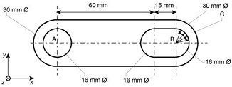
Figure 1 Slotted link in a production machine. Thickness = 4.0 mm; Point A can be taken as the origin for local coordinate system
The TMA report
We wish to determine the likely stresses, deflections and temperature distribution in operation of the link.
Your TMA should be an engineering-type report on your analysis and investigations. Ten single-sided pages should suffice to include: an introduction section, verification section, explicit statements and justification of all assumptions, log or input files (in an appendix), results, a compare and contrast (discussion) section and conclusions.
You are required to carry out a finite element modelling and analysis study of the link and write a report containing the modelling, structural analysis and thermal analysis aspects of your study. You should perform three independent analyses:
1. A stand-alone static structural analysis
2. A stand-alone thermal analysis with HTC 10 and 120 W/m2 K
3. Combined thermal-stress analyses with boundary conditions as above.
It should address the following points:
1. Verification of the results by theoretical/analytical structural calculations and modelling e.g. displacements and stresses, and calculation and modelling of temperature distribution.
2. Discussion of your choice of FEA element types for both structural and thermal.
3. Justification and discussion of your mesh density and its effect on the results. Include an image or images of the mesh(es).
4. Discussion of your choice of boundary conditions (loads and restraints). Outline the loading condition acting on the link and maximum stresses. This should include calculations to convert the force acting on the inside of the slot to a pressure load.
5. Consideration of variation in heat transfer coefficients. In the thermal-stress case, investigate the effect of changing from a natural convection, that is, HTC = 10 W/m2 K, to a forced convection, that is, HTC = 120 W/m2 K.
6. Review and presentation of relevant stress measures, including von Mises and principal. Always include displacement plots (if relevant) and discuss what they reveal (inserting a lot of colour plots on their own without discussion of their significance is pointless). Also include various relevant ‘unaveraged' element stress plots and discuss the nature of these plots and what they indicate.
7. Discussion of any assumptions you have made and the justifications for them.
Further analysis
1. In the thermal-stress case, use the load-transfer method (as shown in ANSYS Exercises 19 and 20) as opposed to the direct method. This is because in a thermal-stress analysis, the load is only transferred ‘one way', from thermal to structural and NOT from structural to thermal. In the direct method one can use suitable elements that can handle both structural and thermal analysis.
2. Add convection on the appropriate surfaces and/or lines.
3. Choose a suitable mesh that can be used for BOTH types of analysis. Concentrate your refinement in areas of high gradient.
4. Structure your report so that it has a logical flow within self-contained sections. Don't forget references, if you require them. Only include text and graphics information that are necessary for substantiating your claims (we don't want pages of irrelevant pictures).
Attachment:- TMA report.rar