Reference no: EM133005121
Assignment task is to create RS logic plc for the following questions. Please make sure each plc do not collides with the sample answers attached below the questions even the output is same. And please attach each code in the solution file as well. (basically this assignment is about paraphrasing the plc codes given)
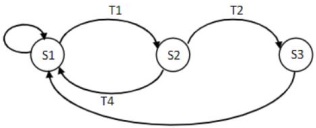
Q1. For the following state transition diagram, as shown in figure 1, write down the state equations and represent the system in a Ladder logic diagram
Q2. A level control is used to control the level of water in a storage tank by turning a discharge pump on or off. The modes of operation are to be programmed as follows:
OFF Position -The water pump will stop if it is running and will notstart if it is stopped.
Manual Made -The pump will start if the water in the tank is at any level except low eg below the low leveL
Automatic Mode -If the level of water in the tank reaches a high point the water pump will startso that water can be removed from the tank thus lowering the level When the water level reaches a low point the p.m p will stop.
Consider a switch for ON/OFF, another switch for MAN/AUTO, and two other switches for low level and high level
If ON/OFF=1, then ON mode, if ON/OFF=0. then OFF mode
If MAN/AUTO=1, then auto mode, if MAN/AUTO=O. then manual mode
Represent the operation with a ladder logic diagram
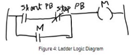
Q3 Find out what is wrong in the following ladder logic diagram. figure 4 Explain and correct the program.
Q4 Convert the following instruction list (Siemens notation) in to a ladder logic diagram. The mnemonics are provided in the Appendix (Page 2). ANB: AND branch. ORB: OR branch
The problem with correct Siemens notations:
A (A10.1 AN 102)0 (A 103 A 10.4) = 02.1
A (A 02.1 0 103) A (A 10.1 0 102) =0 22
Q5 A motor needs to be turned off after it runs for 1 minute. There is a start and stop pushbutton for the motor. The cyclic operation can be reset with a reset pushbutton. The available timer has a time base of 100 ms. Draw a ladder logic diagram to represent the operation of this motor.
Q6. An up/down-counter is used to keep count of the cars that enter and leave a parking garage. As a car enters, the enter switch triggers the upcounter. As a car leaves, the exit switch triggers the downcounter. The Lp counter and downcounter is implemented with the same counter. When the parking lot is full an LED is energized to display the information. The parking can have 100 cars in total. Represent the above operation using a ladder logic diagram.