Reference no: EM13375963
Question 1: Bending about two axes
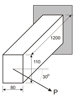
The load P = 2 kN is applied to the end of rectangular section cantilever beam shown at the right. The load acts within the plane of the end face and at an angle of 30° as illustrated. (a) Calculate the magnitude of the moment acting at the build-in (fixed) end and specify the orientation of the moment vector relative to the principal centroidal axes of the section with the aid of a sketch. (b) Determine the stresses at each corner of the built-in (fixed) end of the beam. (c) Specify the orientation of the neutral axis relative to the principal centroidal axes of the section using a sketch. (d) Draw a sketch to represent the stress distribution on the section.

Question 2: Principal centroidal axes
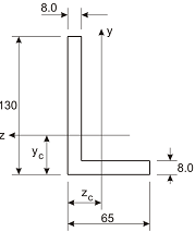
Consider the unequal angle section illustrated in the figure to the right. (a) Calculate the location of the centroid as defined byzc and yc; (b) Determine the values of Iz, Iy, and Izy for the axes illustrated; (c) Calculate the values of Imax and Imin; (d) Show your calculated orientation of the principal centroidal axes (PCAs) on a sketch of the section, noting the axes associated with Imax and Imin values; and (e) Compare your calculated values for Iz, Iy, and the orientation of the PCAs with available data for the section L 130 x 65 x 8 listed in the tables: European unequal angles.jpg, and discuss the differences.

Question 3: Asymmetric bending analysis
This question requires the analysis of data presented on the Study Desk under the heading, Assignment 3 Demonstration. For this demonstration, an unequal angle is clamped at one end and is subjected to a state of bending. Data on the section properties is provided on the Study Desk.
Analysis of the images of the end of the beam is to be performed for comparison with the theoretical results.
In beam bending, the neutral axis defines the orientation of the plane along which direct (normal) strains (and hence, stresses) are zero. The magnitude of the direct strain increases in direct proportion to the distance from the neutral axis and hence the beam deflects in a direction perpendicular to the orientation of the neutral axis.
Required analysis tasks:
(a) Produce a sketch specifying the magnitude and angle of the moment vector relative to the PCAs for the given orientation of the section and the loading.
(b) Using the specified second moments of area and the PCA orientations, determine the expected angle of the neutral axis relative to the horizontal plane and show the neutral axis on a correctly oriented sketch of the section.
(c) Determine the magnitude and location of the expected maximum compressive and tensile stresses within the section when the load is applied.
(d) Analyse the two photographs and account for the measured support rotation effect to specify the horizontal and vertical deflection of the end of the beam that would have occurred if the support was completely fixed. Include a description of the approach you adopted for the analysis of the photographs.
(e) Based on your results in part (d), identify an experimentally-derived orientation for the neutral axis and compare this result with that obtained in part (b) with the aid of a sketch. Discuss possible sources for the differences between the two results.
Question 4: Shear stress in beams
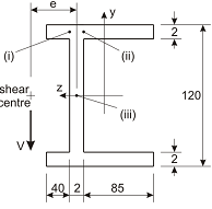
Consider the beam section illustrated in the figure to the right. The beam has a shearing force of V = 5 kN acting vertically through the shear centre as illustrated. (a) Determine the shear stress at the three points in the beam, labelled (i), (ii), and (iii). (b) Produce a plot showing the distribution of shear stress across the beam section, noting the shape of the distributions and key values. (c) Determine the distance e (as shown on the figure) which defines the location of the shear centre of this section. (d) With the aid of a sketch, explain the section rotation that will occur if the line of action of the applied shearing force is through the centroid of the section.
