Reference no: EM13371498
Question 1
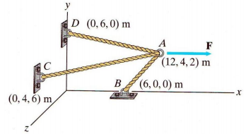
A force of 750 N acts on point A in the x direction where the cables AB, AC, and AD are joined as shown in Figure Q1
The system of force and cable tensions is in equilibrium.
(a) What are the necessary conditions for static equilibrium?
(b) Draw the free-body diagram isolating the system at point A
(c) Express the unit vectors of AB, AC, and AD
(d) Determine the expression of the force vectors of the tension in cables, TAB, TAC, TAD in terms of unit vectors and magnitudes TAB, TAC, TAD
(e) Calculate the magnitudes of the tension in cables AB, AC, and AD for this system in equilibrium
Question 2
(a) What is meant by the centroid of a body?
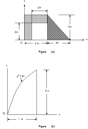
(b) Determine the location (x', y') of the centroid of the composite area with a cutout shown in Figure (a)
(c) Determine the area moment of inertia about Ox for the area shown under the curve in Figure (b)
Question 3
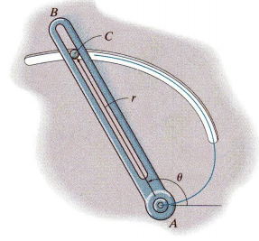
A slotted arm AB drives pin C through the spiral groove described by the equation r = (1.5 θ) m, where θ is in radians as shown in Figure. The arm starts from rest when θ = 60° and is driven at an angular velocity of θ. = (0.4t)rad/s, where t is in seconds.
(a) What is meant by curvilinear motion?
(b) Determine the values of θ, θ., and θ.. when t = 1s
(c) Determine the expressions of r, r. and r.. as function of θ, θ., and θ..
(d) Determine the radial and transverse components of velocity (vr and vθ respectively) of pin C when t = 1s
(e) Determine the radial and transverse components of acceleration of pin C when t = 1s
Question 4
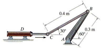
Figure shows a mechanical system where the hydraulic cylinder is extending with a velocity vD = 4 m/s and acceleration aD = 3 m/s2
(a) What is a rigid body? Explain briefly the types of rigid-body plane motion
(b) According to the mechanism shown in Figure Q4, determine the expressions of velocity vectors vB, vC and ωCB in terms of components (i,j,k) and velocity magnitudes vB, vC and ωCB respectively
(c) Calculate the velocity vB of point B and the angular velocity of link BC at instant shown in Figure
(d) Calculate the the angular velocity of crank AB at instant shown in Figure
Question 5
Figure Q5 shows a mechanical system where the mass C of 12 kg is moving down with a velocity of 6 m/s. The mass moment of inertia of drum B is 16 kg.m2 , and it rotates in frictionless bearings. A force P acts on a lever mechanism pressing a brake pad A against drum B, making the system stop its motion in 2 seconds. The coefficient of friction between brake A and drum B is 0.4. g=9.8 m/s2
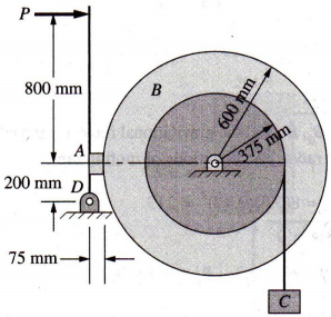
(a) Draw the free-body diagrams for the bar, drum and weight
(b) Determine the tension T in the cable
(c) Determine the friction force necessary to stop the system in 2 seconds
(d) Calculate the value of P necessary for the system to stop in 2 seconds
(e) What power is dissipated by the brake A at the instant when P is applied?
Question 6
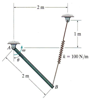
The 20 kg slender rod shown in Figure Q6 is released from rest when θ = 0°. The spring has an un-stretched length of 0.5 m.
Assume g=9.8 m/s2
(a) Explain briefly the different types of potential energy
(b) Calculate the stretch length s1 and s2 of the spring when θ = 0° and θ = 90° respectively
(c) Determine the expressions of kinetic and potential energy of the system when θ = 0° and θ = 90° respectively
(d) Calculate the angular velocity of the rod when θ = 90°
