Programmable Logic Controllers Assignment

Assignment Help Electrical Engineering
Reference no: EM132480340

Programmable Logic Controllers - Teesside University

Programmable Facilities And Additional Facilities

Question 1. Design and draw a ladder diagram circuit suitable for a PLC which will fulfil the following control requirement:

A momentary push switch is to be recognised, remembered and used to switch on an output for a period of 30 seconds. After 30 seconds this output is to be switched off and must be off for 0.5 seconds before a second output switches on.

The second output remains on until a second push switch is operated to turn it off. If the second push is operated at any time then the current output must turn off and the system await the press of the first push. The rungs of the ladder diagram must contain interlock contacts which prevent both outputs being on at the same time.

Question 2. Redesign and improve the pelican crossing ladder diagram given of FIGURE 1 of lesson PLC - 6 - 2 by adding timer rungs and counter rungs between rungs 12 and 14 (or any similar workable scheme) together with the necessary contacts inserted in the amber and green man lights of rungs 7 and 10, etc. The chart below shows the required sequence of events. Note that a section of the chart is repeated a total of 16 times. The time intervals are given below.

Time periods 1 2 3 4 5 6 7 ....... 35 36 37
Green road light ON ON OFF OFF OFF OFF .......... OFF OFF ON
Red road light OFF OFF OFF ON OFF OFF .......... OFF OFF OFF
Amber road light OFF OFF ON OFF ON OFF .......... ON OFF OFF
Wait sign OFF ON ON OFF OFF OFF .......... OFF OFF OFF
Green man OFF OFF OFF ON ON OFF .......... ON OFF OFF
Red man ON ON ON OFF OFF OFF .......... OFF OFF ON

                              first occurrence                          sixteenth time

Time period 1 is the 'normal' conditions.

Time period 2 is after the pedestrian presses the push button.

The change from period 2 to period 3 can only be made after at least one five second check of the road sensors.
The time interval between 3 and 4 is 4 seconds. The time interval between 4 and 5 is 10 seconds. The time interval between 5 and 6 is 0.5 seconds. The time interval between 6 and 7 is 0.5 seconds.

It is not necessary to show the whole of the traffic light ladder diagram of lesson PLC - 6 - 2, only rungs which have been modified. There must, however, be a comprehensive explanation of the operation of the modified rungs accompanying the modified ladder diagram.

Question 3. The chart below shows a required set of step sequences with the same time interval between steps.

Provide a ladder diagram and a comprehensive explanation as a solution for this chart by using two eight-bit shift registers (SFT0 controls relays 50 to 57, SFT1 controls relays 60 to 66). The sequence is to have an initial start signal and thereafter can be free running. A reset control and timer to clock the shift registers must be provided.

STEP No.                   OUT0    OUT1   OUT2       OUT3 OUT4 OUT5

RESET                        all outputs off                                  RESET

1                               ON                                                                         1

2                               ON      ON                                                             2

3                               ON      ON       ON                                                3

4                                          ON       ON      ON                                    4

5                                                      ON      ON       ON                        5

6                                                                ON       ON      ON            6

7                                                                            ON      ON            7

8                                                                                       ON            8

9                                                                                       ON      ON            9

10                                                                          ON       ON      ON           10

11                                                              ON      ON       ON                       11

12                                                  ON       ON      ON                                   12

13                            ON      ON       ON                                               13

14                            ON      ON                                                            14

15                            ON                                                              STEP 1 and 15

Return to step 2

Question 4. (a) An A/D conversion circuit with 10 bit resolution has an input range of 0 - 5 V. A second has a 12 bit resolution and an input range of 0 - 10 V. Calculate the digital output value that will represent a 2 V input for both of the A/D converters. Convert the digital levels in both cases to hexadecimal and then to binary values.

(b) Explain briefly from what you notice about the digital output values in (a) why a digital output value of an A/D converter is rarely the exact same digital value as the analogue input value.

(c) State briefly why a PLC A/D module haveing 4 analogue input channels would probably not incorporate 4 internal A/D circuits.

(d) State briefly which of the two digital output values in (a) is the more accurate and why.

Question 5. Explain briefly the technique of multiplexed switching of analogue signals.

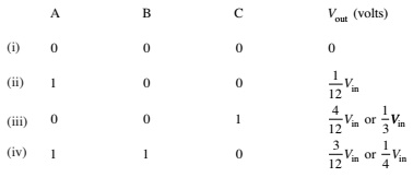
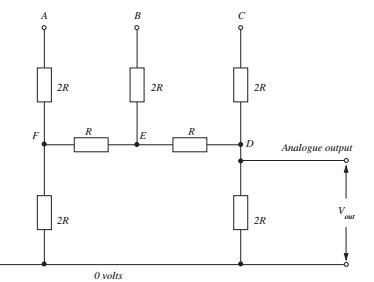
Question 6. The diagram of FIGURE 1 shows a 3 input R/2R digital to analogue converter circuit. By working back from the output (or otherwise) to find the equivalent input resistance in order to determine the input voltage, show that the output voltage values for the following digital input combinations are as shown below.

2295_table.jpg

1047_figure.jpg

Question 7. State briefly:

(i) what is meant by a LAN
(ii) types of LAN
(iii) an application of LANs
(iv) the types of cable likely to be used in a LAN
(v) the meaning of RTU
(vi) what the current title of EIA-422 is and to what it relates
(vii) to what the protocal IEEE-488 relates.

Attachment:- Programmable Logic Controllers.rar

Reference no: EM132480340

Questions Cloud

What is something new that you learned from the talk : What is something new that you learned from the talk or what did it make you consider in your life? What dimension of health are you out of balance or need.
Wake of controversies involving police : In the wake of controversies involving police and members of the African American community, there is a lot of talk about whether or not race is still
Do these shows adequately depict society : 1. Do these shows adequately depict society? 2. Why are they appealing? 3. How do these shows reflect the norms and values of society?
Describe your feelings when you made some sort of move : Describe your feelings when you made some sort of move in your life: a change of jobs, homes, vacation spots, schools, etc. Choose a dominant impression.
Programmable Logic Controllers Assignment : Programmable Logic Controllers Assignment help and solution, Teesside University - assessment writing service - Explain briefly the technique of multiplexed
Foundation of the structure of the city in harappa : Which theory will be the foundation of the structure of the city in Harappa be like?
Globalization making the world more weak-fragile : globalization making the world more weak-fragile
Create an invitation for families to attend the event : Create an invitation for families to attend this event. Be sure it looks professional, while also getting families excited about it and explaining importance.
Canada before during coronavirus : Is globalization bringing us/canada together in a way it has never brought us/canada before during coronavirus?

Reviews

len2480340

3/27/2020 12:56:19 AM

Hi, this is my first time using this. Is it possible to get solutions for the attached questions. Thanks.

Write a Review

Electrical Engineering Questions & Answers

  Ratio of depth to width of the strongest beam

Prove that the ratio of depth to width of the strongest beam that can be cut from a circular log of wood having diameter d is 1.414

  Estimate the inductance of the capacitor

An X7R type 0.022 µF capacitor has a dissipation factor (1 kHz, 1 V (r.m.s.)) of 1.5% and a self-resonance at 30 MHz. Given that the e.s.r. at resonance is 0.056

  Design a 4-bit increment-by-2 circuit with carry out binary

Use contraction beginning with a 4-bit adder with carry out to design a 4-bit increment-by-2 circuit with carry out that adds the binary value of 0010 to its 4-bit input. The function to be implemented is S=A+0010.

  Determine worst signal to quantization noise voltage ratio

Suppose f=20kHz and linear quantization is adopted. Calculate the PCM code when t0=10μs, maximum quantization error, the dynamic range, and the best and worst signal to quantization noise voltage ratio.

  Create etch a sketch using the video screen as the display

Also, if the cursorreaches the end of the screen it should wrap around to the otherside of the screen. If no direction is designated, the cursorshould stay put. Also, the system should show the direction selected on a set of 8 LEDs. When the curso..

  Write algorithm to subtract 32 from fahrenheit temperature

Write a main program to call a procedure that converts the Fahrenheit temperature value stored in the location labeled TdegF to its Celsius equivalent. The range of temperatures is 32°F to 212°F. The procedure stores the converted temperature

  State the types of dc motors

Based on emf and torque equation compare and contrast the two methods of speed control of dc motor.

  Design a first order low pass filter with a dc gain of 2

design a first order low pass filter with a DC gain of 2 and a gain of -3 decibels at 1000 rad/s. not sure what design equations to use since there not seem to be a given cut off frequency.

  Compute the error energy for the approximations

Use the results in Example 6.12 to represent the signal g(t) in Fig. P6.5-8 by Legendre polynomials.

  Find the electric field at a point (0, +5x10^-10m)

Consider a dipole where there is a charge of -6 uC at the point (2X10^-10 m,0) and a charge of +6 uC at the point (+2X10^-10 m,0).

  Which would alternate giving distance to school and to home

An indecisive student contemplates whether he should stay home ortake his final exam, which is being held 2 miles away. Starting at home, the student travels half the distance to the exam venue before changing his mind.

  Calculate the value of the unmarked capacitor

For the circuit shown in Fig. 3.34 the total capacitance is 16 pF.

Free Assignment Quote

Assured A++ Grade

Get guaranteed satisfaction & time on delivery in every assignment order you paid with us! We ensure premium quality solution document along with free turntin report!

All rights reserved! Copyrights ©2019-2020 ExpertsMind IT Educational Pvt Ltd