Reference no: EM132301837
Programmable Logic Controllers (PLC)
Scenario 1:

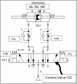
The figure above shows a spring-centred pneumatic cylinder controlled by a PLC. Indications from the figure are as follows:
• 1BL - Electronic position sensor, left
• 1BC - Electronic position sensor, centre
• 1BR - Electronic position sensor, right
• 1A1 - Double acting cylinder, double ended piston rod, spring centred, adjustable cushioning on both sides, position detection
• 1VL - Adjustable exhaust throttle, speed moving left
• 1VR - Adjustable exhaust throttle, speed moving right
• 1VC - 5/3 Control Valve, spring centred, centre exhausted, 2 x solenoids 1YL & 1YR, exhaust terminals (3, 5) that is open without any silencers
• Operation:
• 1YL energised - Solenoid, pressurize right-, exhaust left chamber, piston moves left
• None energised - Centre, Spring-return at both sides
• 1YR energised - Solenoid, pressurize left-, exhaust right chamber, piston moves right
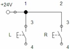
Electrical pushbutton circuit:

On activation of pushbutton L or R the cylinder has to react as follows:
|
L
|
R
|
Reaction of Cylinder
|
|
0
|
0
|
Initial (centred) rest position of cylinder, both solenoids turned off
|
|
0
|
1
|
Only move if in centre position. Move to the right (piston travels 100ms, stay 200ms in final position
and then return to rest position)
|
|
1
|
0
|
Only move if in centre position. Move to the left (piston travels 100ms, stay 200ms in final position
and then return to rest position)
|
|
1
|
1
|
not allowed, to be ignored
|
Sensors and actuators are connected to the PLC inputs and outputs as follows:
|
Inputs
|
Variable
|
Outputs
|
Variable
|
|
I1
|
L
|
Q1
|
1Y1
|
|
I2
|
R
|
Q2
|
1Y2
|
|
I3
|
1B1
|
Q3
|
|
|
I4
|
1B2
|
|
|
|
I5
|
1B3
|
|
|
Question 1:
a) List all your assumptions.
b) Write a PLC program in LD to implement the specified behaviour of the pneumatic cylinder.
c) Provide evidence in the form of appropriate, neat visualization to proof that your circuit operates as specified.
Scenario 2:

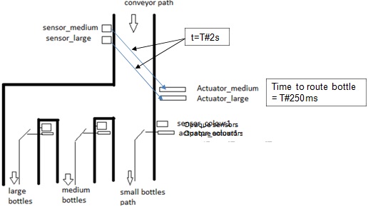
Consider the conveyor-based bottle sorting system shown, through which bottles will pass for final packaging. In terms of size, there are three types of bottles namely
• short,
• medium &
• long.
In terms of bottle type, three opaque sensors are installed which senses bottles to be
• transparent (0) or
• opaque (1).
There are sensors and actuators for medium and large bottles. After size is sensed (medium or large), it takes 2 seconds for a bottle to reach the corresponding size actuator and the actuator must be energised for 0.25s to move a bottle to its correct exit channel.
In each exit channel (small, medium and large exit channel) a sensor senses transparent versus opaque bottles. Moving from the sensor, it takes 0.25 seconds for a bottle to reach the corresponding actuator and the actuator must be energised for 100ms to move a bottle to its correct exit channel.
The sorting system is switched on and off using a Start and Stop button actuating a latching circuit.
|
Inputs:
|
Outputs:
|
|
Start
|
Actuator_medium
|
|
Stop
|
Actuator_large
|
|
Sensor_medium
|
Actuator_ opaque1
|
|
Sensor_large
|
Actuator_ opaque2
|
|
Sensor_ opaque1
|
Actuator_ opaque3
|
|
Sensor_ opaque2
|
|
|
Sensor_ opaque3
|
|
Question 2:
a) List all your assumptions.
b) Write a PLC program in ST to implement the specified behaviour of the actuators.
c) Provide evidence in the form of an appropriate, neat visualization to proof that your circuit operates as specified.
d) The bottles on the conveyer belt are still loaded onto the conveyer belt by hand. Sometimes it happens that a bottle-carrier position is empty because the manual loading operation failed. Production now raises a concern that they don't have an accurate count of the number of bottles processed on the line. Describe how the design can be improved to provide an accurate count of the number of bottles processed.
Scenario 3:
There are various frameworks used by individuals in industry to complete PLC projects. The headings of 2 of these frameworks are given below.
Framework A
1) Design Phase
2) Specify Equipment Phase
3) Configuration Phase
4) Programming Phase
5) Testing Phase
6) Installation Phase
7) Commissioning Phase
8) Documentation Phase
Framework B
1) Definition of control task
2) Determination of control strategy
3) Development of functional design specification
4) Understanding cause and effect
5) Choose a programming language
6) Develop program structure
7) Create documentation
8) Program simulation, verification and commissioning phase
Question 3:
a) Tabularise the merits and shortcomings that you see in each of the above two frameworks.
b) Suggest your own framework that, in your view, is the better option.