Reference no: EM13178046
Scenario
You have been asked to lead a software development team to build a system fulfilling the Statement of Need specified in project 1. Your team is employed by a small company. The customer wants a project that balances reasonable development cost, timely delivery, software quality, and functionality.
In this project, you will refine your analysis, scenario and behavioral models from projects 1 by:
• Describing the interface and component-level design for the B&B software
• Updating your Architectural Context Diagram (ACD)
• Updating your analysis models from project 1.
Completing this project will require that you produce a software design specification document (SDD) that shows how the system shall be structured to satisfy the requirements described in your SRS. The SDD that you create will have consequences for Projects 3 and 4.
SDD Templates
Please use the IEEE std 1016-1998 to develop your SDD. The IEEE Recommended Practice for Software Design Descriptions, standard 1016 is posted in the Reserved Readings section on the Class Menu. Read this to become familiar with the information required in the SDD. Annex A, figure A.1 gives a sample SDD Table of Contents. Use this as a general outline.
The assignment
1. Complete the template as best as you can. Make any reasonable assumptions based on your understanding of the problem that allow you to address as many sections of the SDD template as possible. (Please read the "project descriptions" in the project description section of the syllabus for additional context and information on course projects).
Pay special attention to the following phases of design as you complete the SDD template. The bulk of your grade will be decided on how well you address these issues.
• Data Design: This phase produces the data structures
• Architectural Design: This phase produces the structural units, or classes.
• Interface Design: This phase specifies the interfaces between the units
• Procedural Design: This phase specifies the algorithms of each method.
Note that specific sections of the SDD template speak to the above 4 design phases.
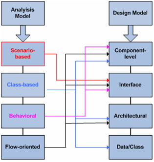
A key objective in the design phase is to translate and map the outputs or deliverables from the requirements model into the four design models.

Hints and suggestions: At a minimum, I expect:
• An updated data model (class diagram or ERD) from project 1. Represent the data model as a table so that you can reflect the attributes of the object.
• An updated Architectural Context Diagram (ACD).
• Software interface description: Perform an interface task analysis for B&B. The goal is to identify and define the interface objects and the actions that are applied to them. You need to specify the component-to-component interfaces (how they are connected) and the human-to-computer interface (textual description of the interface for each user type). (See our online conference discussions on interface design. Also, review the Interface Design Principles and Guidelines outlined in the basic rules for HCI (Human-Computer Interaction) Design noted in the Module 3 commentaries for more on user interface design). Include the following as part of your response:
o A graphical user interface for B&B that shows ( 1) Layout of the objects for the primary user interface (e.g., buttons, menus, images) and a description of their function and (2) Relevant information and flow of information to be displayed to the customers (e.g., rooms, calendar).
• An updated ACD that maps to your updated DFD from project 1 (refined to its lowest possible level) to illustrate the major processes necessary to implement the functionality. Make sure you provide supporting textual descriptions for all processes in the Level 1 DFD. You may need to add a Level 2 DFD to ensure sufficient detail. (See Module 3. Figure 3.4-Level 1 and Level 2 DFDs for Self-Service Checkout System for an example of what is required). When drawing your DFDs remember to adhere to the guidelines specified below Figure 3.4.
When drawing DFDs, you should adhere to the following guidelines:
• Each process should have at least one input and one output data flow.
• Each process should transform the input data flow into a new output data flow.
• Each data store should have at least one data flow.
• Each external entity should have at least one data flow.
• Each process should be identifiable with a unique number at each level.
• Each data flow should be associated with at least one process.
Make sure your work is neat and legible. Your charts, illustrations and diagrams can be done using any word processing, drawing, and/or software CASE drawing tool (or by hand) as long as it is neat and organized. Embed or scan any diagrams that you create in your SDS document-do not upload them separately.