Reference no: EM133150001
Unit 45 Industrial Systems - Pearson Higher Nationals in Engineering
Learning Outcome 1: Apply practical and computer-based methods to design and test a measurement system
Assignment Brief:
Scenario:
You are working as a test engineer for an electronics company and are currently working on measurement circuits for control systems.
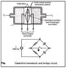
One of your colleagues is developing an electronic thermometer that consists of a potential divider with a thermistor. The voltage out of the potential divider circuit will be fed into a microcontroller which will calculate the temperature, and the device has been passed onto you to test the accuracy and calibration. Another colleague has come to you needing help with a current sensing system. He is currently working with a Capacitive pressure sensor, but he is not sure what the readout of the system would be as pressure increases and was wondering if there is a more effective system to measure pressure. The pressure sensor will be used to measure the pressure of compressed natural gas in a storage cylinder. The sensor is normally supplied with a signal conditioning bridge circuit, a 2500 Hz signal source and an amplifier which generates the sensor output which is calibrated for pressures over a given range. A diagram of the sensor is given below.
Task 1:
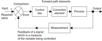
Your colleague has also stated that his system design assumes that the voltage output of the sensor is measured with an ideal voltmeter. The voltmeter has two outputs. One output which feeds a digital display for visually monitoring the pressure read by the sensor, and another output which is an eight bit digital output that is normally used to input the pressure read to a digital controller. What are the assumptions made that make the ideal voltmeter model? Critically evaluateby considering any problems that can arise with using a real voltmeter instead of its ideal counterpart when the voltmeter is used as part of an automatic pressure control measurement system equivalent to the one in the diagram below, as a result you will need to complete the following before doing this:
i) Using TINA-TI simulation software, design a circuit that will read the voltage output of a thermistor for both an NTC and a PTC thermistor.
ii) Run a DC analysis of the system monitoring the system between 0°C and 100°C from the software, Displaying the testresults on a graph.
Explain the use of practical testing by giving a description on why and how you would docarry out this for the above measurement system
Explain one analytical method of doing the same testing and why would this method be used, citing any advantages and disadvantages.
Note that you will be monitored during this exercise to validate your ability to correctly perform this task. All simulation results is to be saved (print screen picture of circuits and instrumentation) as evidence to be submitted.
Interpret the behaviour of the Capacitive pressure gauge.
What are other methods of developing a pressure measurement system for electronic circuitry?
Interpret the behaviour of the Capacitive pressure gauge.
What are other methods of developing a pressure measurement system for electronic circuitry?
Attachment:- Industrial Systems.rar