Reference no: EM1376304
Preparing CAD geometry for FEA, element selection, meshing and mesh optimisation as well as model simplification. In the first part of this assignment you will be required to numerically analyse the structural performance of a slewing jib crane using a few different methods. You will follow the logical CAE analysis flow by starting with a highly simplified model and verifying your results with simple hand calculations. After this you will increase the geometric complexity of your model and identify the model set up that leads to sufficient model accuracy combined with the lowest calculation time.
Introduction
In this assignment you will be required to apply the skills you have learnt in the lectures in the areas of preparing CAD geometry for FEA, element selection, meshing and mesh optimisation as well as model simplification.
In the first part of this assignment you will be required to numerically analyse the structural performance of a slewing jib crane using a few different methods. You will follow the logical CAE analysis flow by starting with a highly simplified model and verifying your results with simple hand calculations. After this you will increase the geometric complexity of your model and identify the model set up that leads to sufficient model accuracy combined with the lowest calculation time.
Design Brief
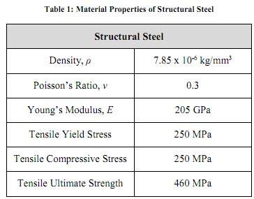
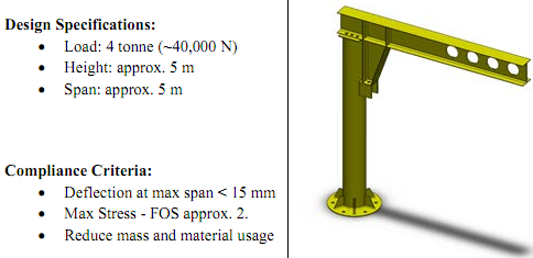
Cranes'R'Us has employed you to assess the structural integrity of the initial design of the slewing jib crane shown in Figure 1. The crane will carry a maximum load of 4 tonnes (~40,000N). The crane is manufactured from a structural steel grade (provided in the ANSYS Material Library) and the material data is supplied in Table 1.
The customer requires that the slewing jib crane must not deflect over 15 mm when loaded at its maximum span and that the stresses not surpass the yield stress, in fact a safety factor of approx. 2 is required.
The client has provided you with a detailed CAD model of the final slewing jib crane assembly, to begin your analysis. This can be seen in Figure 1b).
Project Requirements/Tasks:
The project is broken down into 5 key tasks:
1. Quickly assess the structural integrity of the crane by using an idealised beam element model. You must assess whether the current design meets the compliance (deflection) and maximum stress criteria.
2. Validate your initial beam model with a simple hand calculation to ensure your FEA model is accurate.
3. Provide some design recommendations to the client. You do not need to perform or analyse any design changes, but comment on where design improvements could be made based on the results from your analysis.
4. Establish a more detailed, yet still efficient, FEA model of the final design provided to you by the client. To complete this you will need to: a. simplify/de-feature the geometry provided to you to establish a shell-based FE model,
b. apply the appropriate FE meshing techniques to ensure an accurate yet computationally efficient solution, you will be assessed on the quality of your mesh,
c. assess your models mesh convergence,
d. assess the designs structural feasibility,
e. justify and discuss all the modelling decisions you have made.
5. Compile a concise and comprehensive technical CAE report for the client using the reporting template provided. Do not exceed the table sizing for each section. Therefore, you must be concise and dot-points are encouraged. You must describe both FEA model setups and your findings with regard to the design feasibility. Give a justification for all design simplifications you made and show how you established a converged, accurate and efficient FE model.
To complete these tasks will require extensive modelling work but the time frame for the project is tight. Your role in the team is to develop numerical models that combine sufficient model accuracy with the lowest possible calculation time to allow the project to be completed in time and successfully.


Figure: Design specification and compliance criteria of the slewing jib crane b) Image of the highly detailed CAD model provided by the client.
CAE Technical Report
Introduction and Problem Description
- Describe the problem in your own words and describe the approach you will use to tackle it.
- Identify the customer's needs and translate these into project design targets.
- Give a justification for the geometry you have created. Why do you think it represents the structure sufficiently? Include screenshots to display your simplified model.
- Describe the element type you have used and why? What cross-section geometry have you used? What meshing strategy have you used - remember this is a high-level approximation analysis?
- Give details of the boundary conditions you have used and justify your approach.
- Demonstrate suitable accuracy by using a simple hand calculation for the static analysis of the structure. Describe in detail the hand calculations performed to validate the final solution. What is the approximate error between the simplified hand-calculation and your FEA model? Does the result make sense?
- Finally provide your initial assessment of whether the crane meets the performance criteria. Show images/graphics of your analysis results to verify your findings.
- Give a justification for the geometry and element selection you have used. What feature have you simplified/de-featured/repaired to develop your FE model and why? Include screenshots to display your simplifications.
- Describe the element type you have used and why? What meshing strategies have you used to establish good quality and converged mesh solutions?
- Give details of the boundary conditions you have used and justify your approach. Provide some comments if additional boundary conditions could be applied to simplify the problem?
- Finally provide your assessment of whether the crane meets the performance criteria. Show images/graphics of your analysis results to verify your findings and discuss the findings of your higher order FE model with the simplified Beam model.
- Based on the results of your analysis and your engineering judgement provide some design recommendations to improve performance and reduce material consumption for the crane design.