Reference no: EM132372202
System Analysis and Design
Case Study: Your IT Support Crowd Pty Ltd.
Background:
Your IT Support Crowd Pty Ltd (YITSC) is an Adelaide based Information Systems Support company. While also supporting various types of small to medium size businesses, YITSC specialises in supporting resort management, real estate and legal businesses with their specialist equipment and software requirements. These businesses have strict legal requirements around network security and data privacy because of their Trust Account management software and the sensitive client and guest data stored on the system including credit card details, and other very personal information.
Roger Ben, a senior partner at YITSC, has been talking to clients about updating the security of their systems and how they back up their data. A legal requirement for Trust Account management is secure Offsite Backup of all trust account related data. Roger knows that while some clients are happy to backup to a third party ‘Cloud', most are unsure of the security of cloud-based backups. Furthermore, some YITSC clients are part of corporate businesses or franchises who would like to backup centrally to their own servers. Roger and his partners discussed how they could cater for and all their client's requirements and yet retain oversight and control of the backup system.
They came up with the following concept (Figure 1):
• CLIENT - the client's system where the data is stored that requires backup. The ‘CLIENT Backup' application is installed on any computer or server with data that needs to be transferred to a backup server
• SERVER - there is a range of different backup storage options such as third-party cloud, YITSC servers, or an offsite corporate server. The ‘SERVER Backup' application stored on these systems receives and stores data from the ‘CLIENT Backup' application
• CONTROLLER - YITSC central ‘CONTROLLER' application system remotely sets up and runs the ‘SERVER Backup' application and then remotely sets up and runs the ‘CLIENT Backup' application to send data to the ‘SERVER Backup'. The ‘CONTROLLER' will log and monitor the backups and shut down the SERVER and CLIENT Backups when the data has all been transferred to backup storage.
Roger and his team have designed and tested the CLIENT and SERVER backup applications. For this they have adapted the rsync open source application which will take care of the efficient transfer of data for backup. Currently they can manually set the rsync based SERVER running and the rsync based CLIENT will successfully transfer data to the SERVER. However, while Roger and his team have worked out the secure virtual private networking (VPN) between CLIENT, SERVER and CONTROLLER, they are unsure as to how to design the central CONTROLLER application and organise the CLIENT and SERVER setup information on the CONTROLLER system. Roger has approached you and asked for your assistance. He has some idea about the process the CONTROLLER would use, but he is unsure how to design or model the new system. Roger has asked you to concentrate on designing and modelling the CONTROLLER system only.
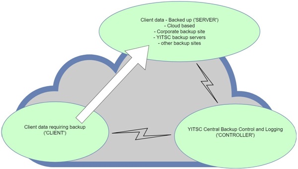
Figure 1- YITSC Offsite Backup concept
Roger stated that the typical CONTROLLER process would start by YITSC IT Team setting up and storing the business entity details. The business entity can be either the business client needing data backed up, or the supplier of data storage for the backed-up data. The backup task details for both the CLIENT and SERVER are entered and stored, and then the backup tasks are scheduled to run at a particular time and interval. The backup would be run according to the scheduled timing.
The CLIENT will send data to the SERVER to be backed up. The CONTROLLER would receive a file transfer activity log and monitor that the backup was proceeding as normal. Roger would like the log activity to be stored in a log file for reference purposes, however whenever an error is logged he would like the CONTROLLER to notify him immediately by email.
The final entry received in the log will notify the CONTROLLER when the backup is finished, at which point the CONTROLLER will first stop the CLIENT, then stop the SERVER and email a summary report to Roger.
When a business client no longer requires the backup service Roger will remove the scheduled backup from the CONTROLLER and, after 6 months, will manually remove the client's backed up data from SERVERs not owned by the client.
At this stage Roger is only concerned with backing the data up. Although he would like to create a ‘restore data' option on the CONTROLLER, he realises that this could be prone to error and decided not to include it in this project.
Business Processes:
A JAD session with Roger revealed the following information. The business processes described below are the system requirements for modelling this information system solution:
• Although there are many possible system entities, the core CONTROLLER system revolves around Business entities, computers that host SERVER and CLIENT backup applications and data (Data Host Controller Computers), backup tasks, and a task scheduler.
• Business entities includes businesses wanting data backed up and businesses able to store the backed-up data. Roger would like Business Entity records to include contact name, business name, contact address, start date and business ABN
• Data Host Controller Computers host the SERVER and CLIENT backup applications. They also have direct access to the data to be backed up (CLIENT Host computer) or the stored backed up data (SERVER Host computer). Your team has decided that data host controller computers will record a computer name, IP address, data version date and time, total data storage capacity, current storage size, data storage path, comments and a Boolean isCurrent attribute.
• Each Business Entity must have one or more Data Host Controller Computers. Each Data Host Controller Computer must have one or more Business Entity objects.
• Each Backup Task records a task name, task comment, and task type (‘server' or ‘client'). These tasks are categorized as one of the following:
o CLIENT Tasks - these tasks are the settings to send data to be backed up to a SERVER Task. Records kept include rsync dash option, rsync dash dash option, rsync module name, and Log file path.
o SERVER Tasks - these tasks are the settings to receive data to be backed from the CLIENT Task. Records kept include server tcp port address, rsync module name, and Log file path.
• Each SERVER Backup Task and each CLIENT Backup Task must have only one Business Entity Data Host Controller. This connects the Backup Tasks to the Business Entity and the Data Host Controller from which the Backup Task can access both the network Addresses and Business name. Each Business Entity Data Host Controller may have many SERVER Backup Tasks and CLIENT Backup Tasks.
• Task Schedule records include a schedule name, status (in progress, scheduled, complete), start date and time and a latest finish date and time.
• Each Task Schedule must have only two Backup Tasks - a CLIENT Task and a SERVER Task. Each Backup Task may have many Task Schedules.
• The Task Schedule will match a CLIENT task with a SERVER task and schedules the tasks to run as a pair.
End of Case Study
Question 1: Essay
Part A - Essay
Gabrielle is a business focused YITSC partner. Although Gabrielle understands project and event management from a business perspective, she has a limited understanding of IT projects. Gabrielle understands that competently managing the development of this backup CONTROLLER project will help ensure that the CONTROLLER service will work well as per the system requirement, will meet budget, and be developed and deployed in a timely fashion. However, her research on information system project management has confused her a little. She came across terms such as ‘Systems Development Life Cycle' and ‘Agile' and has asked you to explain how these relate to the CONTROLLER Project.
The Systems Development Life Cycle (SDLC) defines six (6) core processes.
a) Describe each of the:
I. core processes (figure 10.5) in relation to the CONTROLLER project (15% marks) and
II. core process activities (hints: Figures 11.5 and 11.12 as a start) the project would require for each of these processes (15% marks).
b) Outline what ‘Agile' means in relation to Information Systems projects and how it would be applied in the CONTROLLER project (15% marks).
Roger, Gabrielle and their partners are your target audience for this essay. They are executive business people and some of them have limited understanding of computer terminology.
Your essay should be no less than one thousand five hundred (1500) words and it would be best to be no longer than two thousand (2000) words long.
Appropriate referencing is required. The textbook Satzinger et. al is a valid resource, however it is expected that at least five (5) other resources will also be used. Consult Rubric in Appendix A for more details on how this question will be marked.
Part B - Modelling and Diagramming
Review the YITSC case study and answer the following questions with reference to the information in the case study.
Do NOT extend the scope for any of the following solutions beyond that specifically described in the case study above.
You are permitted to make reasonable assumptions where necessary but these should be noted.
It is recommended that you review all documentation for this case study before finalising any single solution. Ensure that the required consistency has been included within and between each question solution. Consult Rubric in Appendix A for more details on how these questions will be marked.
Question 2: Use Case Modelling
a) Event Table
Review the YITSC case study and prepare an event table for the information system to support the business processes as described. Use at least the following headings for the Event Table:
|
Event
|
Event Type
|
Trigger
|
Source
|
Activity/Use Case
|
System
Response/ Output
|
Destination
|
b) Use Case Diagram
Review the YITSC case study and your event table solution from question 3a above to prepare a Use Case diagram for the supporting information system.
Solutions must follow the methodology as outlined within the Satzinger et al (2016) textbook. Solutions are expected to align with the components as shown in figures 3-12 and 3-15. Consult Rubric in Appendix A for more details on how this question will be marked.
c) Use Case Description
Prepare a fully developed Use Case description for the ‘Create Offsite Backup Task' use case, as documented in the event table solution and the use case diagram solution.
Solutions must follow the methodology as outlined within the Satzinger et al (2016) textbook. Solutions are expected to align with the components as shown in figure 5-2. Consult Rubric in Appendix A for more details on how this question will be marked.
Question 3: Domain Modelling
a) Domain Model Class Diagram
Review the YITSC case study to prepare a domain model class diagram for the supporting information system.
Solutions must follow the methodology as outlined within the Satzinger et al (2016) textbook. Solutions are expected to show:
• The class name and attributes list for each class and sub class as required
• All required associations
• All attributes as specifically mentioned in the case study must be reflected
• Other attributes as needed to support the described functionality.
It is not necessary to show methods, however you may include them if you wish. Solutions are expected to align with the components as shown in figures 4-16 and 4-21. Consult Rubric in Appendix A for more details on how this question will be marked.
b) Design Class Diagram
Prepare a Design class diagram for the Task Schedule and Backup Task classes ONLY. These two classes should be part of the Domain model class diagram solution for the previous question.
Each of these design class diagrams are expected to have a complete attributes list and a comprehensive methods list which supports the specified functionality as described in the case study.
Solutions must follow the methodology as outlined within the Satzinger et al (2016) textbook. Solutions are expected to align with the components for the ‘Design class diagram Student' as shown on the right hand of figure 12.4. Consult Rubric in Appendix A for more details on how this question will be marked.