Reference no: EM13545530
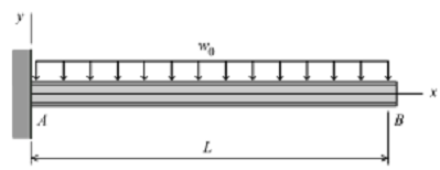
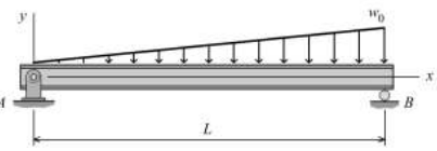
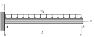
1. For the cantilever beam and loading shown in Figure,
(a) derive equations for the shear force V and the bending moment M for any location in the beam. (Place the origin at point A.)
(b) plot the shear-force and bending-moment diagrams for the beam, using the derived functions.
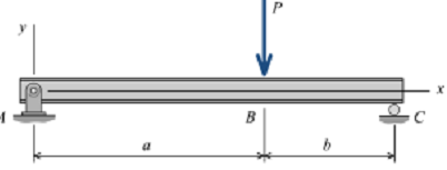
2. For the simply supported beam shown in Figure,
(a) derive equations for the shear force V and the bending moment M for any location in the beam. (Place the origin at point A.)
(b) plot the shear-force and bending-moment diagrams for the beam, using the derived functions.
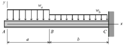
3. For the cantilever beam and loading shown in Figure,
(a) derive equations for the shear force V and the bending moment M for any location in the beam. (Place the origin at point A.)
(b) plot the shear-force and bending-moment diagrams for the beam, using the derived functions
4. For the simply supported beam subjected to the loading shown in Figure,(a) derive equations for the shear force V and the bending moment M for any location in the beam. (Place the origin at point A.)
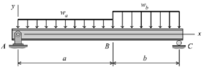
(b) plot the shear-force and bending-moment diagrams for the beam, using the derived functions.
5. For the simply supported beam shown in Figure,
(a) derive equations for the shear force V and the bending moment M for any location in the beam. (Place the origin at point A.)
(b) plot the shear-force and bending-moment diagrams for the beam, using the derived functions.
(c) determine the location and the magnitude of the maximum bending moment.
5. A high-strength steel [E = 200 GPa] tube having an outside diameter of 80 mm and a wall thickness of 3 mm is bent into a circular curve having a 52-m radius of curvature. Determine the maximum bending stress developed in the tube.
6. A high-strength steel [E = 200 GPa] band saw blade wraps around a pulley that has a diameter of 450 mm. Determine the maximum bending stress developed in the blade. The blade is 12-mm-wide and 1-mm-thick.
7. The boards for a concrete form are to be bent into a circular shape having an inside radius of 10 m. What maximum thickness can be used for the boards if the normal stress is not to exceed 7 MPa? Assume that the modulus of elasticity for the wood is 12 GPa
8. A beam having a tee-shaped cross section is subjected to equal 12 kN-m bending moments, as shown in Figure . The cross-sectional dimensions of the beam are shown in Figure.
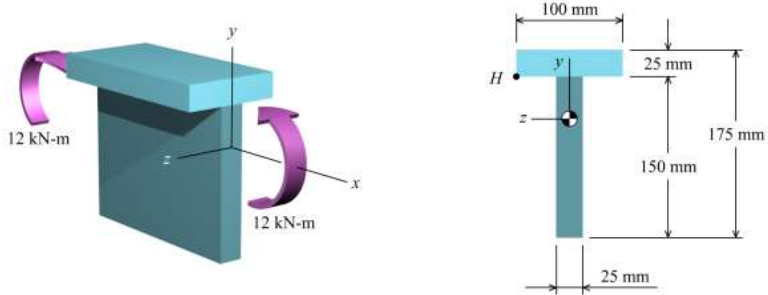
Determine (a) the centroid location, the moment of inertia about the z axis, and the controlling section modulus about the z axis.
(b) the bending stress at point H. State whether the normal stress at H is tension or compression.
(c) the maximum bending stress produced in the cross section. State whether the stress is tension or compression.
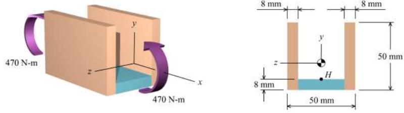
9. A beam is subjected to equal 470 N-m bending moments, as shown in Figure. The crosssectional dimensions of the beam are shown in Figure P8.7b. Determine
(a) the centroid location, the moment of inertia about the z axis, and the controlling section modulus about the z axis.
(b) the bending stress at point H. State whether the normal stress at H is tension or compression.
(c) the maximum bending stress produced in the cross section. State whether the stress is tension or compression
10. Determine the normal stress in a ball (Figure), which has an outside diameter of 185 mm and a wall thickness of 3 mm, when the ball is inflated to a gage pressure of 80 kPa.
11. A tall open-topped standpipe (Figure P14.9) has an inside diameter of 2,750 mm and a wall thickness of 6 mm. The standpipe contains water, which has a mass density of 1,000 kg/m3
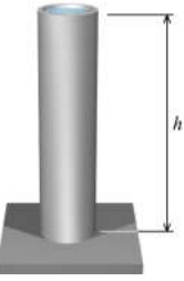
(a) What height h of water will produce a circumferential stress of 16 MPa in the wall of the standpipe?
(b) What is the axial stress in the wall of the standpipe due to the water pressure?
12. The cross-sectional dimensions of a beam are shown in Figure .(a) If the bending stress at point K is 35.0 MPa (T), determine the bending stress at point H. State whether the normal stress at H is tension or compression.(b) If the allowable bending stress is 165 MPa, determine the magnitude of the maximum bending moment Mz that can be supported by the beam.
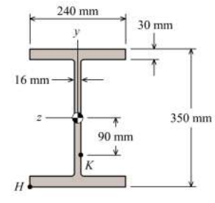
13. Determine the maximum and minimum hoop stress across the section of pipe of 400 mm internal diameter and 100 mm thick, when the pipe contains a fluid at a pressure of 8 N/mm2.
14. Derive the relation between shear force and bending moment?
15. For the cantilever beam and loading shown in Figure 15.1
(a) derive equations for the shear force V and the bending moment M for any location in the beam.(Place the origin at point A.)
(b) plot the shear-force and bending-moment diagrams for the beam, using the derived functions
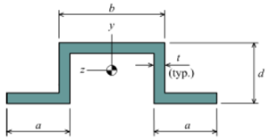
16. The cross-sectional dimensions of the beam shown in Figure 16 are a = 20 mm, b = 60 mm, d = 50 mm, and t = 4 mm. The internal bending moment about the z centroidal axis is Mz = -1,250 N-m. Determine
(a) the maximum tension bending stress in the beam.
(b) the maximum compression bending stress in the beam.
17. A solid circular steel shaft having an outside diameter of 35 mm is subjected to a pure torque of T = 640 N-m. The shear modulus of the steel is G = 80 GPa. Determine
(a) the maximum shear stress in the shaft.
(b) the magnitude of the angle of twist in a 1.5 m length of shaft.
18. A solid stainless steel [G = 86 GPa] shaft that is 1.8 m long will be subjected to a pure torque of T = 120 N-m. Determine the minimum diameter required if the shear stress must not exceed 55 MPa and the angle of twist must not exceed 5°. Report both the maximum shear stress τ and the angle of twist φ at this minimum diameter.
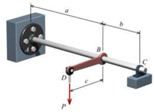
19. A simple torsion-bar spring is shown in Figure. The shear stress in the steel [G = 80 GPa] shaft is not to exceed 70 MPa, and the vertical deflection of joint D is not to exceed 10 mm when a load of P = 11 kN is applied. Neglect the bending of the shaft and assume that the bearing at C allows the shaft to rotate freely. Determine the minimum diameter required for the shaft. Use dimensions of a = 1400 mm, b = 600mm, and c = 175 mm.
20. A typical aluminum-alloy scuba diving tank is shown in Figure. The outside diameter of the tank is 175 mm and the wall thickness is 12 mm. If the air in the tankis pressurized to 18 MPa, determine
(a) the longitudinal and hoop stresses in the wall of the tank.
(b) the maximum shear stress in the plane of the cylinder wall.
(c) the absolute maximum shear stress on the outer surface of the cylinder wall.