Reference no: EM132316346 , Length: word count:2000
Digital Communications Assignment - Simulation of a Communication System using MatLab
Purpose of the assessment (with ULO Mapping) - This assignment is designed to provide students opportunities to develop skills related to the following learning outcomes:
a. Compare multiple input and multiple output systems in modern digital communication systems;
b. Apply the concept of multiuser communication and resource sharing;
c. Simulate digital communication applications using Matlab and hardware devices.
Purpose of the assessment: The purpose of this assignment is to understand the fundamentals of communication systems in the presence of noise, develop programming skills in Matlab, and write technical reports.
Group formation: The group size should be two or three. Contributions from each member must be included in the report.
Description of the assessment:
1. Background -
Digital communication has been evolving rapidly over the past two decades. Systems have developed to achieve data rates from few kilobits per second in 1990's to hundreds of megabits per seconds in 2015. This was supported by many technological advancements such as multicarrier communication (OFDM), multiple antenna techniques (MIMO), high spectral efficient modulation schemes and superior error-control coding.
Despite all the technological innovations, the fundamentals of digital communication systems remain the same. Therefore, learning about basic operations of a telecommunication system would assist understanding more complex advanced systems.
2. Requirements - This assignment shall address the following three areas:
1. In this section the students are required to carry out a literature review on
a) Digital modulation schemes (at least three types) used in digital communications.
b) Various types of models (at least three types) used for wireless channels.
c) Approaches used to correct errors that occur during communications.
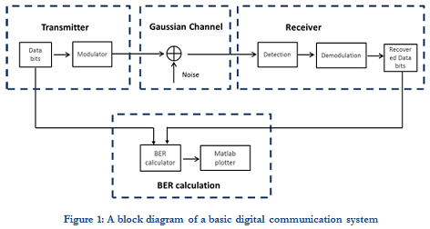
2. The basic functional block diagram of a telecommunication system is shown in Figure 1. Please note that this is a simplified model. Therefore, functions available in an actual system may differ from this.
a) Implement the communication system in Figure 1 in Matlab using m code.
b) Save your codes as .m file.
Specifications for the Communication system:
a. Data bit generation: Use random integer generation function to create random '0' s and '1's (Refer to Labs Manuals or online resources for further information).
b. Modulation: Use BPSK modulator with symbol energy of 1 (one). (Refer to Labs Manuals or online resources for further information).
c. Channel: Add randomly generated number with given noise variance. Noise variance is calculated according to the SNR which is a variable. (Refer to Labs Manuals or online resources for further information).
d. Symbol detection: Detect according to the conventional BPSK symbols constellation symbol boundaries (Refer to Labs Manuals or online resources for further information).
e. Demodulation: Assign '0's and '1's for your symbols (Detection and demodulation can be done together as well) (Refer to Labs Manuals or online resources for further information).
f. Bit-error rate calculation (BER): If a data bit is different from a recovered bit, then we say there is an error. BER is calculated by counting the total number of errors and then dividing by total number of data bits used. (Refer to Labs Manuals or online resources for further information).
Instructions for Simulations:
g. Calculate BER for total of 105 bits (per SNR). (Refer to Labs Manuals or online resources for further information).
h. Calculate BER for SNR values from 0 to 12 dB. SNR is defined as Energy per symbol to Noise variance. (Refer to Labs Manuals or online resources for further information).
i. Plot BER vs SNR curve in Matlab as a figure.
j. Change the modulation scheme to QPSK and generate BER vs SNR graph for QPSK. (Modify steps a to i accordingly).
k. Plot BER vs SNR curves for both BPSK and QPSK in the same Matlab figure.
l. Describe the two graphs BER vs SNR relationship for BPSK and QPSK.
3. Answer the following questions using your knowledge of digital communication and using the above simulation results.
a. Assuming a Gaussian channel, it can be observed that QPSK has more bit errors than BPSK at the same channel SNR.
Does it mean QPSK is a poor modulation scheme? If so why do engineers use QPSK instead of using BPSK?
b. Assume you need to obtain a lower BER around 10-8 at SNR of 10 dB. If the channel remains same as a Gaussian channel, then what can you do to reduce the BER?
Suggested approach:
1. The students are encouraged to undertake a literature review on fundamentals of digital communications (e.g. lecture materials, textbook and online resources).
2. The students are required to complete the Matlab based laboratory materials. Use the previous laboratory sessions and help from Matlab documentation to write a Matlab code to simulate the system to complete the tasks given above.
3. The students are required to interpret the simulation results. Explain the figures from telecommunication engineers' point-of-view.
4. The students are required to answer the questions with the help of prior understanding and simulation results.
5. The students should compile a report including the literature review, Matlab simulation results, discuss results and answers to questions. Matlab code/s should be submitted separately.
6. Clearly mention the names and student numbers of all the group members.
Note - Need the matlab code and report as well.
Submission Guidelines: Your assignment should be completed according to the General Guidelines for Presentation of Academic Work.
1. Successful completion of required tasks
2. Quality of figures
a. comments
b. meaningful names
3. Accompanying documentation including
a. table of contents and page numbers
b. a front page - indicating students name and contribution
c. list of references used (IEEE style).
4. The report must be submitted in soft (electronic) copy under provided link in moodle course page. The page numbers of the assignment must be clear on each page.
5. The Matlab code must be submitted to the provided link in moodle unit page.
Attachment:- Assignment File.rar