Part-1q1 illustrate the radio frequency system of an

Assignment Help Electrical Engineering
Reference no: EM13376434

Part-1

Q1: Illustrate the radio frequency system of an amplitude modulated transmitter using block diagram. Explain the function of each stage of the transmitter and how is this related to stages connected at the input and output of each stage.

Q2: Using block diagram illustrate an AM modulator explaining the function of each block. Using Multisim or any other relevant software:

a. Produce an AM signal with the following parameters:

Carrier frequency:                                 fc = 100kHz

Message frequency:                              fm= 800Hz

Modulation index:                                       m=1

b. Detect and reproduce (demodulate) the message signal. Measure the frequency of the detected signal and compare that with the frequency of the message.

Provide screenshots for modulated and demodulated signals with their relevant information

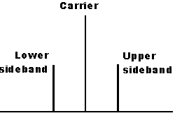
Q3: Figure 1 shows the spectrum of a double sideband full carrier (DSBFC).Calculate the frequencies of the DSBFC spectrum. Suggest a method and present your calculation to detect the lower side band at the output. This should produce a single sideband frequency spectrum knowing that the parameters of the spectrum are:

Carrier frequency:                                  fc = 10kHz

Message frequency:                              fm= 150Hz
1098_Frequency-modulated transmitter.png

Part-2

Derive a system diagram for a frequency-modulated transmitter and explain the function of each stage

Analyse angle modulation

Q1:Illustrate the radio frequency system of a frequency modulated transmitter using block diagram. Explain the function of each stage of the transmitter and how is this related to the stages connected at the input and output of each stage.

Q2: For the following parameters, use Multisim or any relevant software to:

a.    Produce an FM modulated signal:

Carrier frequency:                                   fc = 5kHz

Message frequency:                              fm= 500Hz

Modulation index:                                        ?=5

b. Analyse the effect of changing the modulation index to ?=2 and ?=8. Discuss the changes resulted in the FM output

Task 3

Draw a block diagram of an AM tuned-radio frequency (TRF) receiver and explain its operation

Tuned Radio Receivers are of the oldest receivers that were used until World War 2. Draw a block diagram for a TRF radio and give an explanation to the function of each stage an the operation of the complete TRF radio.

Task 4

Explain the principle of operation of the superheterodyne receiver

Superheterodyne receiver, that sometimes called superhet, uses frequency mixing principles to convert the received radio frequency signal to a fixed intermediate frequency (IF). Electronically, the new IF signal can easily be processed than the received radio carrier frequency. Using a block diagram, explain the principle of operation of the superheterodyne receiver and the function of each stage.

Task 5

Explain the necessary arrangements for transceiver operation

Having a transmitter and receiver working separately such as radio station (only transmitter) and home radios (only receiver) is not difficult. Difficulties arises when both transmitter and receiver are joined in one circuit board to obtain a transceiver that transmit and receive signals. Explain the necessary arrangement needed to overcome these difficulties and for the transceiver to operate safely.

Reference no: EM13376434

Questions Cloud

A car tyre is pumped up to 230 kpa what is the volume of : a car tyre is pumped up to 230 kpa. what is the volume of air at atmospheric pressure 100kpa that must be pumped into a
Aviss taxable income for the year is 300000 and bests : aviss taxable income for the year is 300000 and bests taxable income for the year is 425000. for each of the scenarios
Record and collate relevant data where appropriatea use : record and collate relevant data where appropriatea use appropriate research project techniques.b interpret and analyse
Task 1nbsp determine the bandwidth and expected information : task 1nbsp determine the bandwidth and expected information capacity of typical communication systems q1a describe the
Part-1q1 illustrate the radio frequency system of an : part-1q1 illustrate the radio frequency system of an amplitude modulated transmitter using block diagram. explain the
This case study shows how the absence of serious bafflers : this case study shows how the absence of serious bafflers to entry is likely -to -influence the price of flat-top tv
1 suppose that boston scientific is considering making an : 1. suppose that boston scientific is considering making an investment of 500 million in a new stent production
Research and select two professional journal articles that : research and select two professional journal articles that directly relate to team building or improving team
1suppose the term structure of risk-free interest rates is : 1suppose the term structure of risk-free interest rates is as shown below a.calculate the present value of an

Reviews

Write a Review

Electrical Engineering Questions & Answers

  Lithium ion battery technology

The paper includes Lithium ion battery technology with its advantages and disadvantages. The paper discusses about the Lithium air battery in which detailed reactions of Lithium with air including nonaqueous as well as aqueous are given.

  Power transformers and tariffs

Construction of different types of power transformer, significant energy savings

  Paper on orthogonal frequency-division multiplexing

This document is shown a paper on Orthogonal frequency-division multiplexing with advantages, disadvantages and uses.

  Function of the hmi in a scada system

This assignment contains electronics engineering questions like State the commonly found components of a SCADA (Supervisory control and data acquisition) system. and decribe the function of the HMI in a SCADA system.

  Resultant waveform of the odd harmonic series

Prepare an Excel graph showing the individual components and summated resultant waveform of the odd harmonic series resulting in an approximate square wave.

  Explain scada system

Explain the function of the HMI in a SCADA system.

  Design a 2-digit 24 second shot-clock

Design a 2-digit 24 second "shot-clock" countdown timer with pushbutton controller.

  Model a discrete-time system

To understand di erent signal models To be able to model a discrete-time system and design simple signal processing algorithms.

  Draw a relay construction diagram

Draw a relay construction diagram and briefly explain the operation of a relay.

  Frequency division multiplexing

Write a short technical report on Frequency Division Multiplexing

  Impact of electron energy

Briefly discuss the impact of electron energy, electron current and target on the Bremsstrahlung generated.

  Traffic light controller

The schematic of the traffic light controller

Free Assignment Quote

Assured A++ Grade

Get guaranteed satisfaction & time on delivery in every assignment order you paid with us! We ensure premium quality solution document along with free turntin report!

All rights reserved! Copyrights ©2019-2020 ExpertsMind IT Educational Pvt Ltd