Reference no: EM133156465
Assionment: Design of a Octal to 7-segment LED decoder
A common output device used for displaying octal digits of 0-7, decimal digits 0-9, hexadecimal digits or even simple symbols, is the 7-segment LED display shown in Fig. I. Each of the segments in the display which is labelled with standard letters from a to g, is an LED (or Light Emitting Diode) arranged physically in a matrix such that a digit or symbol is displayed when the appropriate segments are lit. For example, to display the digit two (2), the LED segments labelled a,b,g,e and d (as illustrated in Fig 1.) must be lit.
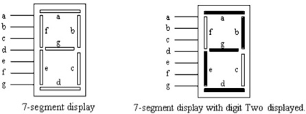
Two types of 7-segment displays are generally available: 'common cathode' and 'common anode'. In the 'common cathode' type of 7-segment LED display, a logic High (or 1) must be applied at the segment input pin to light up the segment. For example, to display digit 2 as shown above, logic High must be applied at the input pins of a,b,g,e and d, while the logic levels at f and c must be Low. In the common anode type of 7-segment display, the opposite logic level is required to turn on an LED segment, i.e. a logic Low input will cause the segment to light.
In order to display octal digits in the range of 0 to 7, an octal-to-7-segment decoder is required as shown in fig.2. This device takes a 3-bit octal input and generates at its outputs, the appropriate logic levels for the 7-segment LED display. For example, to display octal digit '2', the bit pattern `0101 must be applied at inputs C B A of the decoder, with input C being the MSB and A, the LSB The decoder in turn generates the correct logic levels at outputs a, b, c, d, e, f and g so that the correct LED segments are lit to display digit 2. Search the Internet for more information and/or explanation on the 7-segment LED display, if necessary.
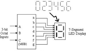
Fig, 2 Octal to 7-segment Decoder
Your assignment is to do a paper design of an octal-to-7-segment common cathode decoder for digits 0, 2, 3, 4, 5 and 6 using the least possible number of NAND gates. You are to assume that only these octal digits are applied to the inputs of the decoder, i.e. combinations for digits I and 7 are never applied. Your solutions must show all the design steps taken, i.e. a description of the task, requirements definition, design approaches such as truth-table(s), simplification using K-maps or Boolean theorems, and the implementation (circuit diagrams) using standard logic symbols. Use a Truth-table format as shown below. You are advised to read up on Topic 4.5 (Kanaugh Map Method) of your text book
|
Octal Inputs
|
Decoder Outputs for Common Cathode
|
|
C
|
B
|
A
|
a
|
b
|
c
|
d
|
e
|
f
|
g
|
|
0
|
0
|
0
|
1
|
1
|
1
|
1
|
1
|
1
|
0
|
|
:
|
:
|
:
|
:
|
:
|
:
|
:
|
:
|
:
|
:
|
|
1
|
1
|
1
|
X
|
X
|
X
|
X
|
X
|
X
|
X
|
On completion of your paper design, you should simulate your circuit using NI Multisim o verify that your solution works. You are required to demonstrate this simulation and submit the simulation file together with your report to your tutor.