Reference no: EM131229115
Problem
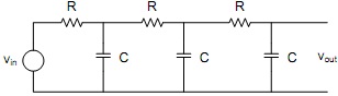
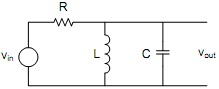
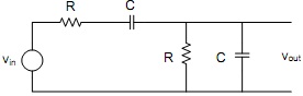
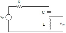
Use SPICE to plot gain, magnitude and phase, for the following circuits as a function of frequency. Mark relevant points on the graphs for comparison with calculation of HW1. State the value(s) of frequency and gain at which the gain is real (Note that Gain = Vout/Vin is a complex quantity in general). Compare the results with your sketches of HW1.
For question 1 use a time constant for each stage of 39 µs and for 3 use a time constant for each network of 15.9 µs. For questions 2 and 4 choose a Q of about 10, and a resonant frequency of 10 kHz. Select reasonable, practical component values. For the graders convenience use a log frequency scale and gain in dB. Note that question 4 looks at a different output than in problem sets 1 and 2.
1. Three equal low pass filter stages.
2. Parallel resonant circuit.
3. Wien filter.
4. Series resonant circuit
5. Use the two diode model linearized as below
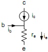
Where β = IC/IB is the current gain, and re is given by the diode equation (m=1) as 25mVe at room temperature. Note: This is a linear model of the transistor. So we are assuming we have biased it at a suitable DC operating point which provides re as a known given value. When using a linearized model we are looking for an AC/small signal analysis.
With emitter grounded calculate
a) Input impedance at the base.
b) Output impedance at the collector
c) Output impedance with a resistor R across the constant current source (from the collector terminal to the base terminal) With base grounded calculate
d) Impedance at the emitter
e) Output impedance at the collector
f) Output impedance at the collector with a resistor R across the constant current source With an impedance R' to ground at the base
g) Impedance at the emitter
|
Create an event-agent-database table
: Books Ga'Lore! needs assistance to document its business processes for the revenue cycle – customer credit card sales. The following is a narrative, along with a list of tables in the Books Ga’Lore! database Books Ga'Lore! sells books. Annotate the n..
|
|
Critical reflection on your key strengths
: A critical reflection (incorporating scholarly references) on your key strengths, values, and other career influences and how these impact your career action plan
|
|
What do you think are the internal stressors
: What do you think are the internal stressors for this situation? Explain your reasoning. What do you think are the potential external stressors for this situation? Why?
|
|
Calculate the resonant frequency
: Calculate the resonant frequency fr - show your work and record the answer in row 1 of the table. Use the Waveform generator to produce an input: 2.5Vpk and frequency set to the resonant frequency.
|
|
Output impedance with a resistor
: Output impedance with a resistor R across the constant current source (from the collector terminal to the base terminal) With base grounded calculate -
|
|
The column will operate at essentially atmosphericpressure
: The wastewater will also contain traces of organic material.6. A packed absorption column 0.5 m diameter, 3 m high, absorbing gaseoushydrochloric acid into water. The column will operate at essentially atmosphericpressure.
|
|
Is this even an appropriate function of federal government
: These are contingencies, and grant funded programs need to plan for them. Now, it's your turn...what kinds of contingencies should grant requesting agencies consider? Personnel? Competition? Weather? Obsolescence? Opposition from the communi..
|
|
About the perfect forecast
: After reading Chapter 18, think of all the examples of forecasting you experience on a regular basis; such as the weatherman on TV each night. Now, considering the technology we have at our disposal today, why can't we get a "Perfect" forecast?
|
|
Transmission delay and propagation delay
: How long does it take for a packet of length 1,000 bytes to be delivered from the sending host to the receiving host over a link of distance 1,200 km, propagation speed 2.4x10⁸ m/s, and transmission rate 10Mbps (consider both transmission delay an..
|