Reference no: EM131864329
Assignment -
The Operating Systems project is divided into three steps:
1. a simple batch system
2. a simple batch system with memory management
3. a multiprogramming batch system with process management
The description of Step 1 will be given in 3 parts:
1. characteristics of the hardware
2. instructions
3. characteristics of the software
1. CHARACTERISTICS OF THE HARDWARE
The computer to be simulated has the following characteristics:
MEMORY - The main memory consists of 256 words (locations 0 to 255). A word is the basic addressing unit. Each word is 16 bits wide.
CPU - The computer being simulated is a stack machine; that is, an architecture which supports one or more stacks.
a. The architecture for this machine supports one stack (5), which consists of 7 registers, each register being 16 bits wide.
S (7 : 1) <15 : 0>
The top element of the stack may be used as an accumulator. Initially, the stack is empty (the Top Of Stack pointer is 0).
b. The Top Of Stack pointer (TOS) points to the current top of the stack. Since there are at the most 7 elements on the stack, 3 bits are necessary to hold the value of TOS.
A value of zero represents an empty stack.
Attempting to decrement TOS below zero results in an illegal instruction trap.
c. The CPU also needs to keep a register for the program counter (PC). The PC is 7 bits wide. Both the PC and the address calculation will allow an individual user segment to address only half of memory.
d. The CPU maintains a register to hold the instruction being executed, called the INSTRUCTION REGISTER (IR). The IR has to be 16 bits wide.
e. A BASE REGISTER (BR) is necessary to hold the base address of the program being executed. It has to be 8 bits wide to address all of memory.
INPUT/OUTPUT DEVICES - Input and output devices are generally simulated by files (for user jobs in loader format, trace files, etc.), however in Step 1 the individual user job I/O is via keyboard/screen.
CLOCK - A system-wide CLOCK will be used to time the execution of programs in terms of virtual time units (vtu). Later in the specification, it will be made clear when the CLOCK is to be incremented.
2. INSTRUCTIONS -
The system supports data of types integer and bit.
The range of integer values may span from -2^13 to (2'13)-1. The values will be represented in 2's complement.
Instruction format will be of 2 types, zero-address and one-address instructions (short or long). Due to the nature of the machine and its high reliance on stacks and stack operations, many instructions are zero address instructions that utilize the top 2 elements of the stack. Furthermore, because of the flexibility introduced through the stack architecture, many operations may be used with both zero and one address.
i. ZERO-ADDRESS INSTRUCTIONS (7 bits)
A zero address instruction is an instruction of the simplest form. This instruction format will utilize the top or top two elements of the stack depending upon the operation to be performed, or will generate a program halt.
FORMAT:
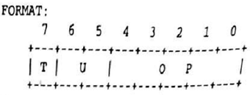
where
T = instruction type (short = 0)
U = unused
OP = op code
FUNCTION:
S(TOS - 1] <- (S(TOS)) op (S(TOS-1))
TOS <- TOS-1
The operator "op" is applied to the contents of the top two elements of the stack and the result is placed on the stack. Or
S(TOS) <- op (S(TOS))
The operator 'op' is applied to and the result is placed on the execution of this instruction. the contents of the top of the stack. TOS does not change with the execution of this instruction.
Whenever possible, there will be two instructions of type 1 per memory word. If it is not possible to have two instructions of type 1 in a word, the unused bits will be padded with zeros (i.e., inserted).
ii. ONE-ADDRESS INSTRUCTIONS (16 bits)
A one-address instruction will contain an instruction type indicator of 1 bit, a 5-bit op code, an indexing bit, and a memory displacement address. This instruction type will also utilize the stack directly for operations requiring more than one operand.
EFFECTIVE ADDRESS CALCULATION
The effective address calculation computes the virtual address of the operand. There are two modes of addressing:
EA = DADDR without indexing
EA = DADDR + (S(TOS)) with indexing
The conversion of the virtual address into a real address is done in the Memory Routine when the contents of the BR are added.
FORMAT:
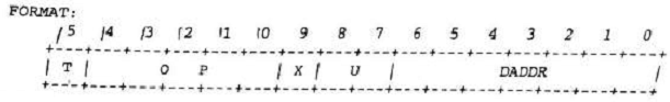
where
0 - 6: displacement addressing
7 - 8: unused
9: index bit (0:no indexing; 1: indexing)
10 - 14: op code
15: instruction type (long = 1)
3. CHARACTERISTICS OF THE SOFTWARE -
SYSTEM (Step 1) will be the driver for this simulation. It will contain modules; LOADER, CPU, MEMORY, and ERROR_HANDLER. LOADER will be responsible for loading user jobs (in loader format) from the input device (a file) into main memory via a LOADER buffer of size four words. A user job has to be converted from HEX to BINARY before it may be loaded. The LOADER will need to access main memory, but this access may be made only via the MEMORY routine.
After the program has been loaded, it has to be executed. The CPU routine will be responsible for execution. Whenever a program terminates, control is transferred to SYSTEM. SYSTEM will then verify if there is another incoming job (i.e., another user job in the input file) and the cycle will be repeated. For step 1, batches are of size one job each, so there should be no cycling.
MEMORY PROCEDURE
MEMORY (X, Y, Z)
X "READ" or "WRITE"
Y memory address (EA)
Z variable
The memory routine is responsible for translating all virtual addresses to real addresses and then performing the actual read or write operation on memory. In the first step of the project, the translation is to simply add the contents of the BR to the virtual address (later it will involve a look-up in the segment tables and page tables).
Notice that this addition of (BR) is done not only to the effective addresses specified in user instructions but also to the PC and to the addresses passed by the LOADER routine.
READ operation: Notice that the READ operation is a MEMORY MANAGER function and NOT the RD operation from the instruction set.
FUNCTION: The contents of Y (memory location EA) will be read into variable Z.
WRITE operation: Notice that the WRITE operation is a MEMORY MANAGER function and NOT the WR operation from the instruction set.
FUNCTION: The contents of variable Z will be written into main memory location Y. Variable Z. may be the top of the stack used by the rpU, a buffer used by the LOADER, or other temporary scratch pad registers needed by the CPU.
LOADER PROCEDURE
LOADER (X, Y)
X -> starting address
Y -> Crate switch
INPUT: The input to your Step]. is a file of hex digits which is a "user job" or 'user program" in loader format. The "input" to the user job, if indeed it requires any input, will be provided at the keyboard.
OUTPUT: It is only the user job's output (more specifically, the result of execution of WR instructions) that is to be displayed on the screen. The following information is to be output to a file (a
virtualized output device) upon completion of a user job. Note that this "output" consists of some information generated by your operating system on behalf of the user job.
1. Cumulative job identification number (this number is reset each time that you start your operating system simulation). This should be I for this step since your simulation will handle exactly one "user job" each time that you run it. The reason is the absence of a multiprogramming memory manager and a scheduler, and the lack of a JCL in Stepl. Consequently, your operating system will run a single job and then stop, there can be no transition to another job, and, therefore, the output file and the trace_file must not be cumulative for the successive runs of your system.
2. Any warning messages resulting from handling a user job.
3. A message indicating the nature of termination: normal or abnormal; and, if abnormal, a descriptive error message.
4. Output of the current user job (if job terminated normally). As mentioned earlier, this is in addition to the output being displayed on the screen.
5. CLOCK value in HEX at termination.
6. Run time for the job in decimal, subdivided into execution time, input/output time, etc. Note that all 'times" refer to virtual time periods as measured by differences between values of the simulated system's CLOCK at different instances.
Attachment:- Assignment File.rar