Reference no: EM133050942
MOD003415 Advanced Computer Aided Engineering - Anglia Ruskin University
Assignment A
Part 1
Task:
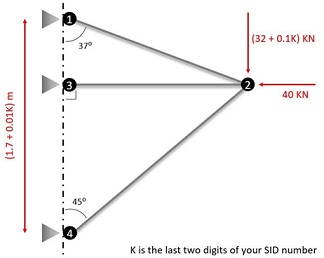
Given E = 200 GPa
Yield strength = 180 MPa
Cross sectional area for all elements = 95 mm2
1) Fully analyse the model using matrix method.
2) Use ANSYS to analyse the model.
3) Compare the analytical and CAE results and comment on the correlation.
4) Comment on the adequacy of sections used. Is there any particular concern that should be addressed before the design is finalised?
Give a comprehensive solution (Only compression and tension is considered).
5) Use CAE to analyse the system again and compare your results with the initial outcome.
Part 2
Figure below shows a prismatic beam under uniformly distributed load. Given that the Young's modulus for the beam is E = 70G Pa, Perform the inquired tasks:
(K is the last two numbers of your SID)
- Using hand calculation or otherwise find the moment of inertia and the location of the neutral axis for the beam.
- Use = My/l, where σ is the stress, M is the bending moment, y the distance I from neutral axis and I is the moment of inertia. to find the maximum stress acting in the middle of the span.
- Use Wmax = 5pl4/384EI
, where p is the intensity of the distributed load and l is the span length, to calculate the maximum deflection at the center of the span.
- Use ANSYS to analyse the structure and find the maximum stress and deflection at the centre of the span.
- Compare the analytical and CAE results. Comment on the differences and the potential reasons for errors.
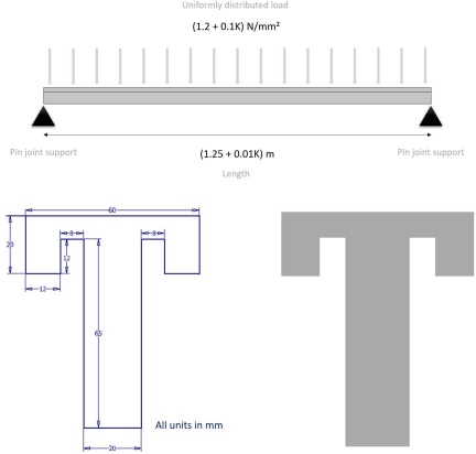
Cross- Part of the beam
Part 3
Figure 1 shows an aluminum wheel rim of a typical urban vehicle. The rim is usually designed against a number of loading cases such as Accelerating, Brake and Cornering etc. In this task you will analyse the rim against brake and cornering forces and will create a load combination case. A356.0 aluminium is used to cast the rim.
a) Given that the mass of the car is 1950 Kg and it turns at a radius of 10 m with linear speed at 45 kph, work out:
- The cornering acceleration of the vehicle
- The cornering force acting on the one wheel patch (a car has four wheels)
b) The car decelerates at a steady 3G rate. Work out the magnitude of the brake load applied in one wheel.
Suppose that the rim is restrained with five nuts (Figure 2) and a stays uniformly against a flat flange as shown in figure 3. Given that the brake and cornering forces are applied uniformly on the entire internal side edge surfaces of the rim is used for the brake load while only internal phase will be used for cornering (figure 2), perform the following tasks:
c) Browse through the model and measure different part to have some ideas about the sizes.
d) Apply solid tetrahedron mesh on the part precisely and maintain 90% of the mesh within 1 and 4 aspect ratio.
e) Apply the brake load evenly tangent to the specified surfaces and analyse the part. Spot the area with high stress concentration and use stress probe to measure the magnitudes.
f) Given that the tyre patch point is located at 110 mm distance from the outer face of the rim, create a rigid contact to apply the nodal cornering force to the specified internal surface and analyse the part. Spot the area with high stress concentration and use stress probe to measure the magnitudes.
g) Create a load combination case from the loads listed above and analyse the part. Spot the area with high stress concentration and use stress probe to measure the magnitudes.
h) Comment on the results for all loading steps ad explain how the assumption may potentially expose error to the results and contribute to their differences with the reality.
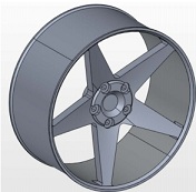
Figure 1
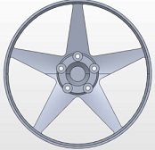
Figure 2
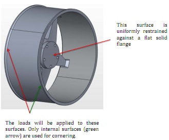
Figure 3
Assignment B
Introduction
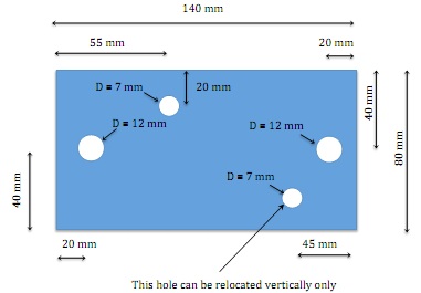
A compliance link is to be designed to give the maximum axial movement between 0.15 mm and 1.2 mm, The weight is to be maintained at minimum, under a load of 450N, with a safety factor of 2, without the material yielding. The load is to be applied by two 11mm diameter pins in two 12 mm diameter holes. There must be two 7 mm diameter assembly holes in the specified area of the part, but other holes can also be allocated to reduce the weight.
The pre-drilled blank to be used is shown in the following diagram.
Assignment Details
Part A
Design a link to fulfill the design requirements incorporating the pre- drilled holes. The minimum radius required around the two 12 mm diameter holes for manufacture is 10 mm radius.
Part B
Optimise the link design to minimise the weight, without compromising safety.
Part C
Use CNC simulation to prepare a suitable CNC program and machine your new design on the machining centre. The cutters available 8, 10 and 15 diameter the station numbers and other data will be given when available. Carry out a test on a material test machine to confirm satisfactory operation with the load plus safety factor. Note the test conditions and results and use them to confirm your FE model.
Part D
Note the test conditions and results and use them to confirm your FE model. Compare with at least one other validation method.
Part E
Submit for assessment a list of the files on the system and a report explaining the work undertaken, the results obtained and your comments and conclusions. You should include details of the FE analyses carried out (such as alternative boundary conditions) and explanations of the rationale employed.
Material data
Aluminium alloy with E = 70 GPa and Yield stress of 124 MPa
Note: need to do ASSIGNMENT 1 only
Attachment:- Advanced Computer Aided Engineering.rar